Introduction to Antenna Input Impedance
An antenna connects to a transmitter or receiver through two terminals. Whatever happens beyond them — radiation, heating, energy stored in the near field — the circuit only sees a voltage V_A and a current I_A at a given frequency. Their ratio is the input impedance, which IEEE 145 defines as "the impedance presented by an antenna at its terminals."
Input impedance decides how much of the available power actually enters the antenna (Part 8), how efficiently that power is radiated (Part 9), and over what bandwidth the antenna can be used (Part 10). It is the single most-measured antenna property, and the first thing a designer tunes.
Definition of Input Impedance
Draw a closed surface around the antenna that crosses the feed at the terminals and extends to the far field. Applying the complex Poynting theorem (Part 5) to the volume inside, the complex power delivered at the terminals splits into three parts:
Resistance and Reactance Components
| Component | Defined by | Physical meaning | Typical values |
|---|---|---|---|
| Radiation resistance R_r | P_rad = ½|I_A|²R_r | Power that leaves as radiation | 0.01 Ω (tiny loop) to ≈ 300 Ω (folded dipole) |
| Loss resistance R_L | P_loss = ½|I_A|²R_L | Heat in conductors, dielectrics and nearby ground | mΩ (thick copper) to tens of Ω (thin steel, poor ground) |
| Reactance X_A | X_A = 2ω(W_m − W_e)/(½|I_A|²) | Net stored energy: inductive if magnetic energy dominates, capacitive if electric dominates | −2000 Ω (short dipole) to +500 Ω (long dipole) |
Only R_r is useful. R_L wastes power, and X_A, although it consumes no power, prevents power from being delivered unless it is cancelled by a matching network.
Radiation Resistance
Radiation resistance is the fictitious resistance that would dissipate the radiated power if it carried the antenna current. It must always be referred to a specific current — usually the feed current, sometimes the current maximum. For the Hertzian dipole (Part 1) it is 80π²(L/λ)². For the half-wave dipole we integrate the far-field power:
Referring R_r to the feed
For a dipole of any length L with the sinusoidal current I(z) = I_m sin[k(L/2 − |z|)], the radiated power is fixed, but the feed current is I_m sin(kL/2). Since ½I_m²R_m = ½|I_feed|²R_in:
Loss Resistance
At radio frequencies, current flows in a thin skin at the conductor surface. The current density decays as e^(−d/δ) into the metal, where δ is the skin depth:
A round wire of radius a ≫ δ behaves like a strip of width 2πa with resistance R_s per square. A short length dz carrying current I(z) dissipates ½|I(z)|²R_s dz/(2πa). Integrating along a half-wave dipole with sinusoidal current and referring to the feed current I₀:
Other loss mechanisms add their own resistances in series: dielectric loss in substrates and radomes (dominant in printed antennas, Part 9), ground loss under monopoles and low dipoles, loss in loading coils and matching components, and current on the outside of a coaxial feed.
Antenna Reactance
Reactance comes from energy stored near the antenna. A short dipole is essentially two small capacitor plates (the arms) far apart: electric energy dominates and X_A is large and negative. A small loop is essentially an inductor: magnetic energy dominates and X_A is positive. As a dipole lengthens towards λ/2, the stored electric and magnetic energies come into balance, and X_A passes through zero.
A transmission-line model
An open-circuited two-wire line of length ℓ has input impedance Z = −jZ₀ cot(kℓ). Treating each arm of a dipole as one conductor of a flared line of length L/2 and average characteristic impedance Z₀ gives a useful approximation:
The induced-EMF method
A more accurate classical result integrates the near field of the assumed sinusoidal current along the wire surface. It yields closed forms in terms of the sine and cosine integrals Si and Ci. For L = λ/2 the result is the textbook impedance:
Relationship Between Antenna Length and Input Impedance
| Wire radius a/λ | Resonant length | R_in at resonance (induced EMF) | L/2a |
|---|---|---|---|
| 10⁻⁵ | 0.488 λ | 68 Ω | 24 400 |
| 10⁻⁴ | 0.485 λ | 67 Ω | 2 420 |
| 10⁻³ | 0.478 λ | 64 Ω | 239 |
| 10⁻² | 0.457 λ | 57 Ω | 23 |
The induced-EMF method slightly under-estimates the resonant resistance of real dipoles: a Method of Moments solution of the 146 MHz, 2.05 mm wire dipole (a/λ = 0.0005) gives 0.479 λ and 71.9 Ω, against 0.480 λ and 65 Ω from the induced-EMF formula. The length is predicted very well; the resistance needs a full numerical solution.
Equivalent Circuit of an Antenna
Over a narrow band around its first resonance, a dipole or monopole behaves like a series RLC circuit; around its anti-resonance (L ≈ λ) it behaves like a parallel RLC. Expanding the reactance in a Taylor series about the resonant frequency ω₀, where X(ω₀) = 0:
More elaborate equivalent circuits — chains of RLC sections, Foster forms with several resonances — reproduce the impedance over a decade of frequency and are used to design broadband matching networks. Physically, the series model has a capacitive reactance below resonance (too short: electric energy dominates) and an inductive reactance above it.
Resonant Frequency of an Antenna
An antenna is resonant at a frequency where its input reactance is zero. Resonance does not by itself mean a good match: a resonant half-wave dipole (≈ 70 Ω) gives VSWR 1.4 on a 50 Ω line, and a resonant monopole on a small ground plane may present 20 Ω. Nor is resonance required for radiation: a non-resonant antenna radiates perfectly well once a matching network cancels its reactance. Resonance is valuable because the impedance there is purely resistive and changes slowly, which makes matching easy.
| Antenna | First resonance | Z_in at resonance | Next resonance |
|---|---|---|---|
| Thin centre-fed dipole | L ≈ 0.47–0.49 λ | 65–72 Ω (series) | L ≈ 0.9–0.95 λ, 1–5 kΩ (parallel) |
| Monopole on large ground | h ≈ 0.24 λ | 32–36 Ω | h ≈ 0.45 λ, high impedance |
| Folded dipole | L ≈ 0.47 λ | ≈ 280–300 Ω | — |
| Rectangular patch (edge) | L ≈ λ/(2√ε_eff) − 2ΔL | 150–400 Ω (inset-feed to 50 Ω) | Higher-order cavity modes |
| Small loop with tuning capacitor | Set by the capacitor | Very small R; transformer-coupled | — |
Input Impedance of a Dipole Antenna
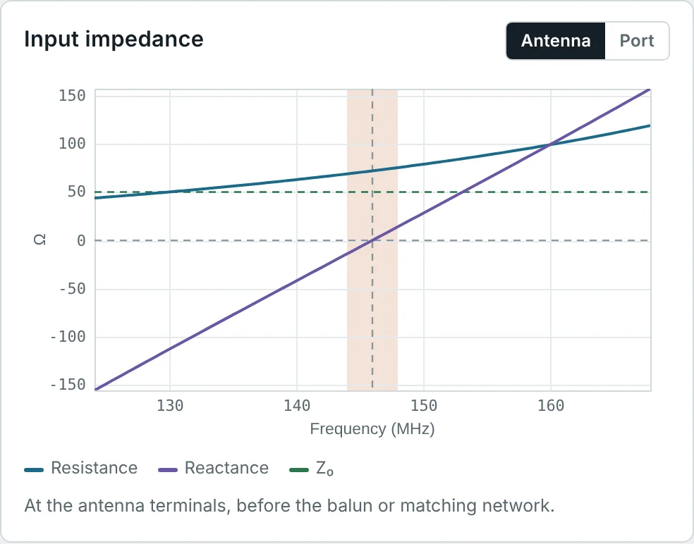
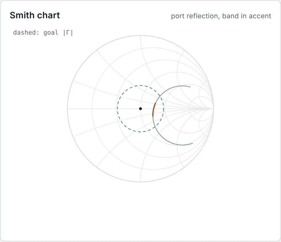
The calculator screenshots show the full frequency response of the 146 MHz dipole. On the Smith chart (Smith Chart & Impedance Matching series) the impedance traces a clockwise arc that crosses the real axis at resonance; the arc is short because a dipole of moderate thickness has a modest Q (Example 7).
Input Impedance of a Monopole Antenna
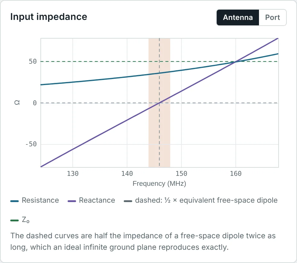
By image theory (Part 2), a monopole of height h on an infinite perfect ground plane produces the same fields above the plane as a dipole of length 2h in free space. It radiates only into the upper half-space, so for the same feed current it radiates half the power, and the feed voltage is half the dipole's (one arm instead of two):
Frequency-Dependent Impedance
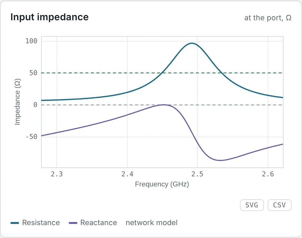
For a fixed antenna, changing frequency changes the electrical length L/λ, so the impedance of Fig 1 is traversed as frequency sweeps. A narrowband antenna (thin dipole, small antenna, patch) has a steep reactance slope and a high Q; a broadband antenna (thick dipole, bowtie, log-periodic, spiral) keeps its impedance nearly constant over a wide range. Comparing the patch and dipole calculator results:
Measuring Antenna Input Impedance
Input impedance is measured with a vector network analyzer (VNA). The VNA measures the complex reflection coefficient S₁₁ at its calibrated reference plane, and the impedance follows from the bilinear transformation of the reflection-coefficient article:
- Calibrate at the antenna terminals. SOL (short-open-load) calibration at the end of the cable, or port extension / de-embedding of the feed line, moves the reference plane to the antenna. Otherwise the cable rotates the measured impedance around the Smith chart.
- Suppress common-mode current. A balanced antenna fed by coax needs a balun or ferrite choke; otherwise the cable shield becomes part of the antenna and the measurement depends on how the cable is routed.
- Mimic the real environment. The reactive near field (Part 3) interacts with nearby objects: measure handset antennas in their housing, ideally with a phantom hand and head.
- Use a clear space. Reflections from walls change the impedance of low-directivity antennas slightly; measure in an anechoic chamber or outdoors for accurate values.
Worked Examples
Radiation Resistance of a Half-Wave Dipole
Problem: Evaluate R_r = (η/4π)Cin(2π) with Cin(2π) = 2.4377 and η = 120π Ω. What feed current is needed to radiate 100 W?
The feed voltage at resonance would be I₀R ≈ 121 V peak. Short antennas with tiny R_r need very large currents (and develop very large voltages across their reactance) for the same power.
Loss Resistance of a Copper VHF Dipole
Problem: The 146 MHz calculator dipole is 0.985 m of 2.053 mm copper wire (a = 1.027 mm). Find δ, R_s, R_L and the radiation efficiency with R_r = 71.9 Ω.
Exactly the 99.7% the calculator reports. Full-size copper dipoles are nearly lossless; losses only matter for thin, poorly conducting or electrically small antennas.
A Stainless-Steel HF Dipole
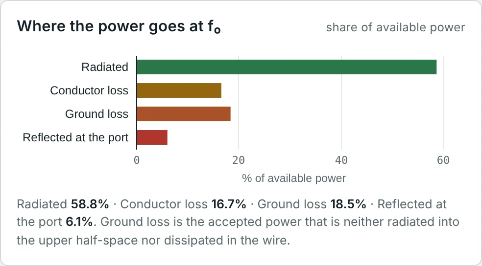
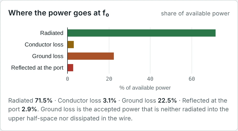
Problem: A 7.15 MHz dipole is 20.6 m of 1.024 mm stainless steel (σ = 1.39 × 10⁶ S/m). Its resonant input resistance over ground is 82.8 Ω. Find R_L and the fraction of the accepted power lost in the wire. Repeat for copper.
The calculator's power budget shows 16.7% conductor loss for stainless steel and 3.1% for copper, of the available power (Part 9). Stainless steel is 42 times less conductive than copper, so its R_s is √42 = 6.5 times larger.
Short Dipole and Its Loading Coil
Problem: A 1 m dipole of 2 mm wire (a = 1 mm) is used at 30 MHz (L = 0.1 λ). Estimate its input impedance and the series inductance needed to resonate it.
A coil with Q = 200 has a loss resistance of 1926/200 = 9.6 Ω, five times R_r: the efficiency would be only 17%. This is the practical limit on short, loaded antennas (Part 9).
Quarter-Wave Monopole Impedance
Problem: Use image theory to find the impedance of an exact quarter-wave monopole on a perfect ground, and the resonant impedance of the calculator's 146 MHz monopole if the matching dipole is 71.9 Ω.
On 50 Ω coax a resonant monopole gives |Γ| = 0.16, VSWR 1.39 (−15.7 dB return loss). Drooping the radials of a ground-plane antenna downward raises the impedance towards 50 Ω.
Impedance from a Measured S₁₁
Problem: A VNA calibrated at the antenna terminals reads S₁₁ = 0.2∠60° in a 50 Ω system. Find Z_A.
A positive phase of S₁₁ corresponds to the upper (inductive) half of the Smith chart. Shortening the element moves the point clockwise toward the real axis.
Q of a Dipole from Its Reactance Slope
Problem: For the 146 MHz wire dipole (a/λ = 0.0005), the induced-EMF model gives R = 65 Ω at resonance, Z = 68.9 + j20.7 Ω at +2% and 61.5 − j20.6 Ω at −2% in frequency. Estimate Q.
A matched series RLC with Q = 8 has a VSWR ≤ 2 bandwidth of 1/(Q√2) ≈ 8.8% (Part 10). The calculator's 6.6% is lower mainly because the dipole is not matched to 50 Ω.
Wire Thickness and Resonant Length
Problem: A 433 MHz dipole (λ = 69.2 cm) is to be made from (a) 1 mm wire and (b) 14 mm tube. Using the table of resonant lengths, estimate the cut length of each.
Thicker conductors have more end capacitance and need more shortening; they also have a flatter reactance (Fig 1) and so a wider bandwidth. The Dipole Calculator's "Synthesize" step does this length correction automatically.
Limits of the Transmission-Line Model
Problem: Estimate the reactance of a 0.45 λ dipole with a = 0.001 λ using the transmission-line model, and compare with the induced-EMF value of −51 Ω.
Near λ/2 the radiation itself shifts the resonance; a lossless line model cannot capture that, and it puts resonance exactly at 0.5 λ instead of 0.48 λ. Use it for intuition and for short antennas, and numerical methods for design.
Why a Folded Dipole Has Four Times the Impedance
Problem: A folded dipole is two parallel half-wave wires joined at the ends, fed at the centre of one. In the radiating mode both wires carry the same current. Derive its input resistance.
The two wires together carry 2I_feed and radiate like one dipole carrying 2I_feed, but only I_feed passes through the feed. The folded dipole is a built-in 4:1 impedance transformer, used in Yagi driven elements and with 300 Ω twin-lead.
Summary
- Input impedance Z_A = R_r + R_L + jX_A follows from the complex power balance: radiated power, lost power and net stored energy.
- Radiation resistance is referred to a stated current; for a half-wave dipole R_r = (η/4π)Cin(2π) = 73.1 Ω, and R_in = R_m/sin²(kL/2) for other lengths.
- Loss resistance comes from the skin effect: R_s = √(πfμ/σ), and R_L = L R_s/(4πa) for a half-wave wire dipole.
- Reactance reflects stored energy: capacitive for short dipoles, inductive for loops and long dipoles; a thin half-wave dipole is 73.1 + j42.5 Ω, resonant when shortened by 2–5%.
- Near resonance an antenna is a series RLC, Z ≈ R[1 + j2Q(ω − ω₀)/ω₀], with Q set by the reactance slope; thicker conductors give lower Q.
- A monopole on a large ground has half the impedance of the corresponding dipole: 36.5 + j21.3 Ω at λ/4.
- Impedance is measured with a VNA calibrated at the antenna terminals, with a balun or choke and in a realistic environment.
An antenna's impedance rarely equals the line impedance exactly. Part 8: Antenna Reflection Coefficient and Return Loss quantifies the mismatch with the reflection coefficient, return loss and VSWR, and shows how to read an S₁₁ plot.
Put It Into Practice
Use the NEXT ANTENNAS calculators to apply the ideas from this article to real antennas.