Introduction to Antenna Directivity
The radiation pattern of Part 4 shows the shape of an antenna's radiation; the radiation intensity of Part 5 puts a number on it in watts per steradian. Directivity combines the two into a single figure of merit: how many times stronger is the radiation in the best direction than it would be if the same power were spread evenly over all directions?
Directivity depends only on the pattern shape. Gain, realized gain and efficiency then account for what happens to the power before it is radiated. Getting these terms straight is essential: the wrong one in a link budget can be off by several decibels. Our introductory guide Antenna Basics gives a shorter overview; this article develops the definitions in full.
The Isotropic Radiator and Its Radiation Intensity
An isotropic radiator is a hypothetical, lossless point source that radiates equally in every direction. It cannot be built, but it is the reference against which every antenna is compared. If it radiates a total power P_rad, that power is spread evenly over the full sphere of 4π steradians:
Maximum Radiation Intensity and the Directivity Equation
A real antenna radiating the same P_rad has a radiation intensity U(θ, φ) that varies with direction. Its largest value, U_max, occurs on the peak of the main lobe. Directivity compares the two:
Since the total power is fixed, an antenna can only increase radiation in some directions by reducing it in others. The isotropic sphere is "squeezed" into lobes: directivity is the factor by which the main lobe pokes out beyond the sphere.
Broadside, both dipoles exceed the isotropic circle; towards the wire axis (θ = 0° and 180°) they fall far below it. The half-wave dipole's beam is slightly narrower than the short dipole's (78° vs 90°, from Part 4), which is exactly why its directivity is slightly higher.
Directivity as an Integral of the Pattern
Directivity can be written entirely in terms of the normalized power pattern. Write the radiation intensity as U(θ, φ) = U_max F²(θ, φ) and add up the power through a large sphere, using the solid-angle element dΩ = sin θ dθ dφ:
Deriving the Directivity of Common Antennas
The integral above turns directivity into a calculation. Four cases cover most of antenna theory, and their results are worth knowing by heart.
Hertzian Dipole: D₀ = 1.5
From the far field derived in Part 4, E_θ = jηkIL e−jkr sin θ/(4πr). The radiation intensity is U = r²|E_θ|²/(2η):
Half-Wave Dipole: D₀ = 1.64
With the half-wave pattern F(θ) = cos(π/2 · cos θ)/sin θ and peak intensity U_max = η I₀²/(8π²), the power integral cannot be done in elementary functions. It reduces to the cosine integral Cin:
cosⁿθ Patterns: D₀ = 2(n + 1)
Many directional antennas radiating into one hemisphere — patches, open waveguides, horn feeds — are well approximated by U = U_max cosⁿθ for 0 ≤ θ ≤ 90° and zero behind. The integral is elementary:
Uniform Broadside Array: D₀ ≈ 2Nd/λ
For N isotropic elements spaced d along a line, integrating the array factor of Part 4 over the sphere gives, for a long array, D₀ ≈ 2Nd/λ — twice the array length in wavelengths. For the common spacing d = λ/2 the result is exact for any N: D₀ = N. Doubling the number of elements doubles the directivity (+3 dB) and halves the beamwidth — the two are two views of the same fact, Ω_A ≈ θ₁θ₂.
Directivity in Linear Scale and in dBi
Directivity is a dimensionless power ratio. It is quoted either as a plain number or in decibels relative to isotropic:
| Antenna | D₀ (linear) | D₀ (dBi) | Typical HPBW |
|---|---|---|---|
| Isotropic (reference) | 1 | 0 | — |
| Short (Hertzian) dipole | 1.5 | 1.76 | 90° |
| Half-wave dipole | 1.64 | 2.15 | 78° |
| Quarter-wave monopole on infinite ground | 3.28 | 5.15 | 39° (elevation) |
| Microstrip patch | 4–8 | 6–9 | 60–90° |
| Yagi-Uda (6–10 elements) | 20–60 | 13–18 | 30–50° |
| Pyramidal horn | 30–300 | 15–25 | 10–40° |
| Parabolic dish, 1 m at 10 GHz | ≈ 6 000 | ≈ 38 | ≈ 2° |
Estimating Directivity From Beamwidths
Evaluating Ω_A exactly needs the full 3D pattern. For a single, well-defined main lobe with small side lobes, a good approximation is to replace the beam by a "pencil" whose cross-section is the two half-power beamwidths θ₁ and θ₂ (in radians): Ω_A ≈ θ₁θ₂. Then:
A second estimate, due to Tai and Pereira, was obtained by fitting cosⁿ patterns. It is more accurate when the two beamwidths are similar:
What Is Antenna Gain?
Directivity assumes all the power fed to the antenna is radiated. Real antennas lose some of it as heat in the conductors and dielectrics. Gain uses the power accepted by the antenna, P_in, instead of the radiated power:
Difference Between Gain and Directivity
| Directivity D | Gain G | Realized gain G_r | |
|---|---|---|---|
| Reference power | Radiated power P_rad | Accepted power P_in | Available power from the source |
| Includes losses? | No | Conductor and dielectric | Losses + impedance mismatch |
| Depends on | Pattern shape only | Pattern + materials | Pattern + materials + match |
| Relationship | D | G = e_cd · D | G_r = (1 − |Γ|²) · G |
Because e_cd ≤ 1, gain is never larger than directivity. Gain is not an amplification: a 6 dBi antenna radiates four times more power density in its best direction than an isotropic antenna fed with the same power — and correspondingly less elsewhere.
Relationship Between Gain and Radiation Efficiency
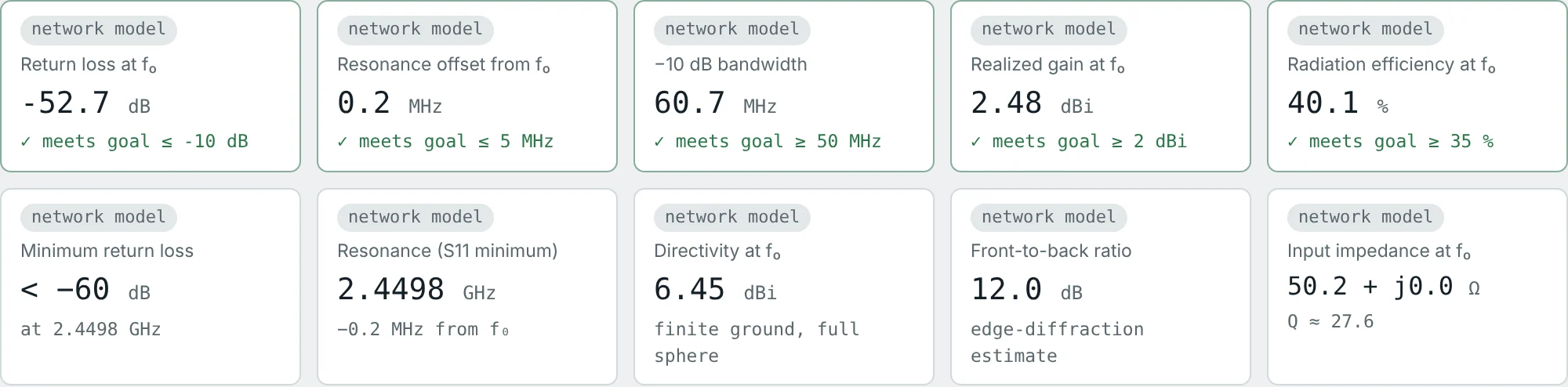
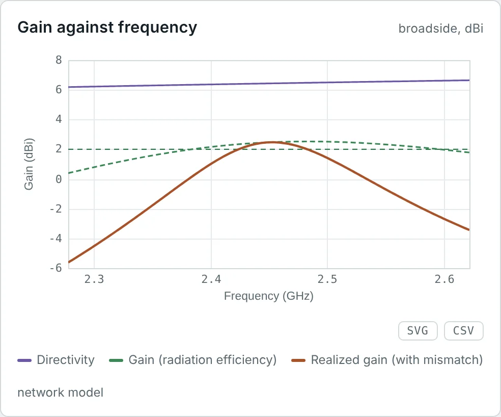
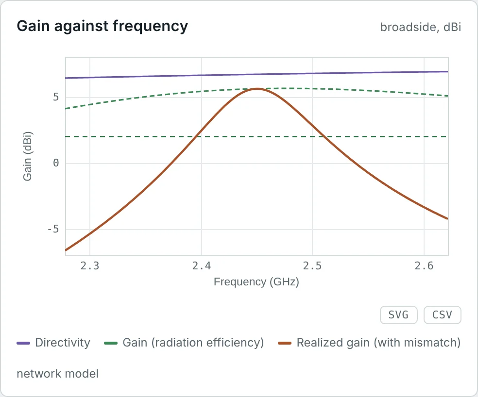
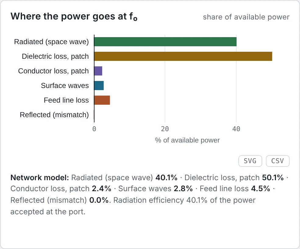
The two patch designs from Part 4 show this clearly. Both are 2.45 GHz inset-fed patches with almost the same pattern — but one is on lossy FR-4 (tan δ = 0.02) and the other on Rogers RO4003C (tan δ = 0.0027):
Gain in dBi and dBd
Gain can be quoted against two references. dBi is relative to an isotropic radiator; dBd is relative to a lossless half-wave dipole, whose gain is 2.15 dBi:
Realized Gain
Gain is defined with the power the antenna accepts. If the antenna is not perfectly matched to its feed line, part of the available power is reflected before it ever reaches the antenna (Part 8). Realized gain includes this mismatch:
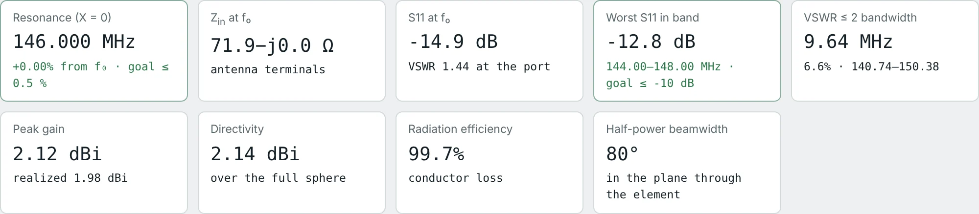
The Method of Moments dipole from Part 4 illustrates all three quantities at once:
Partial Directivity and Polarization
The far field has two orthogonal components, E_θ and E_φ (Part 4), and the radiation intensity is the sum of their contributions, U = U_θ + U_φ. Directivity splits the same way into partial directivities:
Partial directivity matters whenever only one polarization is received. A receiver with a vertical antenna sees only the partial directivity of the vertical component of the transmitter, not its total directivity — one source of the polarization mismatch loss in link budgets.
How Large Can Directivity Be?
Directivity grows with antenna size in wavelengths, and two results bound it from above. For a planar aperture of physical area A, the highest directivity is obtained with uniform illumination:
For an antenna of any shape that fits inside a sphere of radius a, Harrington showed that the "normal" maximum directivity — achievable without impractically large currents and losses — is approximately
Antenna Gain Measurement
Gain is measured in an anechoic chamber or on a far-field range. Both standard methods are built on the Friis transmission equation (Part 13), which in decibels for two antennas a distance R apart reads
Gain-Transfer (Comparison) Method
Measure the received power with a reference antenna of known gain G_ref — usually a calibrated standard-gain horn — then replace it with the antenna under test (AUT) in exactly the same position. Everything else in the Friis equation is unchanged, so it cancels:
Three-Antenna Method
When no calibrated reference exists, measure the transmission between each pair of three antennas A, B and C at a known distance. Each measurement gives one equation in the sum of two gains:
Directivity is obtained by integrating a full 3D pattern measurement with the formula for D₀ above; dividing gain by directivity then gives the radiation efficiency. Electrically small antennas are often measured in reverberation chambers or Wheeler caps, which measure efficiency directly (Part 9).
Numerical Examples of Directivity and Gain
Directivity From Radiation Intensity
Problem: An antenna radiates 10 W. Its maximum radiation intensity is 5 W/sr. Find U₀, D₀ (linear and dBi) and the power density at 1 km, isotropic and on the main beam.
On the main beam at 1 km the power density is U_max/r² = 5.0 µW/m² — exactly D₀ × S₀. The equivalent beam solid angle is Ω_A = 4π/6.28 = 2.0 sr.
A Short Dipole: Directivity and Radiation Resistance
Problem: A 2 cm element at 300 MHz (L = λ/50) carries 1 A peak. Find its directivity, radiation resistance and radiated power.
The directivity is respectable, but with a radiation resistance of a third of an ohm, even 1 Ω of conductor loss would waste three-quarters of the power. Small antennas are limited by efficiency, not directivity.
Directivity of a Half-Wave Dipole
Problem: Using U_max = ηI₀²/(8π²) and P_rad = ηI₀²Cin(2π)/(8π) with Cin(2π) = 2.4377, find D₀, P_rad for I₀ = 1 A, and R_r.
The calculator's Method of Moments solution for a real 2 mm copper wire gives 2.14 dBi and 72 Ω at resonance — the thin-wire theory and the full solver agree closely. Part 7 explains the small difference in resistance.
Designing a Beam for 10 dBi
Problem: A feed antenna has a cosⁿθ pattern in its forward hemisphere. Which n gives 10 dBi directivity? What is its HPBW, and how well does the Kraus formula predict D₀?
A 0.17 dB error is excellent for a two-number estimate. For this broad beam the Tai–Pereira formula gives 8.48 (9.3 dBi) — less accurate here.
Directivity of an Eight-Element Array
Problem: Eight isotropic elements are spaced λ/2 apart in a broadside array. Find D₀ and check it against the long-array formula and the beamwidth from Part 4.
The beam is a 12.8° fan in the plane of the array but omnidirectional around its axis, so the Kraus formula — which assumes a pencil beam — does not apply. Directivity comes from narrowing in one plane only, which is why it grows only as N, not N².
Directivity of a Horn From Its Beamwidths
Problem: A horn has a 30° half-power beamwidth in both principal planes. Estimate its directivity with both formulas.
For narrow beams the two estimates agree within half a decibel; measurement or simulation settles the final figure.
Gain of an FR-4 and a Rogers Patch
Problem: The FR-4 patch has D₀ = 6.45 dBi and e_cd = 40.1%; the Rogers patch has D₀ = 6.72 dBi and e_cd = 77.7%. Find the gain of each.
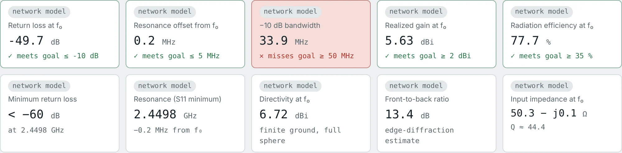
The directivities differ by only 0.27 dB. Almost the entire gain difference is efficiency. Both directivities fit a cosⁿ pattern with n ≈ 1.2–1.4 (D₀ = 2(n + 1) = 4.4–4.7).
Realized Gain and dBd of the Dipole
Problem: The copper dipole has G = 2.12 dBi and S11 = −14.9 dB at its 50 Ω port. Find its realized gain, its gain in dBd, and its total efficiency.
A real copper dipole is 0.03 dB below the ideal lossless dipole that defines 0 dBd. The 72 Ω dipole on a 50 Ω port loses a further 0.14 dB to mismatch — Part 7 explains where the 72 Ω comes from.
Gain-Transfer Measurement
Problem: In a chamber, a standard-gain horn of 15.0 dBi receives −42.3 dBm. The antenna under test, placed in the same position and aligned for maximum signal, receives −45.1 dBm. Both are matched. Find the AUT gain.
If the AUT had a VSWR of 2 (|Γ|² = 0.111), the same reading would be its realized gain; its gain would be 12.2 + 0.51 = 12.7 dBi. Always state which one a measurement reports.
Calibrating Three Antennas Without a Reference
Problem: Three horns are measured in pairs at R = 3 m and 10 GHz (λ = 3 cm). The received-to-transmitted power ratios are −41.0 dB (A–B), −38.5 dB (A–C) and −40.1 dB (B–C). Find all three gains.
Check: G_A + G_B = 20.98 ✓, G_A + G_C = 23.48 ✓, G_B + G_C = 21.88 ✓. At 3 m the far-field condition 2D²/λ ≥ R limits the horn aperture to D ≤ 21 cm.
Summary
- Directivity D₀ = 4πU_max/P_rad compares the peak radiation intensity with that of an isotropic source radiating the same power.
- It depends only on the pattern shape: 1.5 (1.76 dBi) for a short dipole, 1.64 (2.15 dBi) for a half-wave dipole.
- Gain G = e_cd·D₀ includes conductor and dielectric losses; realized gain also includes mismatch: G_r = (1 − |Γ|²)·G.
- Directivity splits into partial directivities for the two polarizations, and is bounded by 4πA/λ² for an aperture and by about (ka)² + 2ka for an antenna inside a sphere of radius a.
- dBi is relative to isotropic, dBd to a half-wave dipole: dBi = dBd + 2.15.
- D₀ = 4π/Ω_A: a short dipole gives 1.5, a half-wave dipole 4/Cin(2π) = 1.64, a cosⁿ pattern 2(n + 1), and a λ/2-spaced array of N elements N.
- Directivity can be estimated from beamwidths (≈ 41 253/θ_Eθ_H) and gain is measured by comparison or the three-antenna method.
Gain depends on how much of the input power the antenna accepts, and that depends on its impedance. Part 7: Antenna Input Impedance and Radiation Resistance looks at the antenna from its terminals.
Put It Into Practice
Use the NEXT ANTENNAS calculators to apply the ideas from this article to real antennas.