Antenna design,
solved in your browser

Free calculators and guides for patch antennas, microstrip lines, Smith chart matching, dipoles and RF exposure. Textbook equations, full-wave checks, and no sign-up.
Try a frequency

Wavelength in air
12.2 cm
Half-wave dipole
5.84 cm
50 Ω microstrip width
3.11 mm
Patch W × L
37.6 × 29.1 mm

Closed-form estimates (Hammerstad, Balanis). Open any result for the full solver.

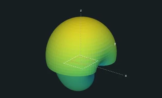
3D radiation pattern of an inset-fed patch antenna at 2.45 GHz, 2.48 dBi peak gain To-scale layout of a 37.58 by 29.30 mm inset-fed patch on FR-4 with dimensions
From the patch antenna calculator: a 2.45 GHz inset-fed patch on FR-4.

Antenna design

Patch antenna calculator

Design a rectangular or circularly polarized microstrip patch from your laminate and frequency, then check it with a 3D full-wave solve before you order boards. Inset feed, quarter-wave transformer or coaxial probe.

  1. Port solver. A 2D finite-element solve finds the 50 Ω feed width and εeff.
  2. Patch synthesis. Width, length, inset depth or probe position, matched at f₀.
  3. Analyze. S11, input impedance, Smith chart, gain, and 2D and 3D patterns.
  4. Optimize. Set goals, sweep a dimension, or run Nelder–Mead.
  5. Yield. Monte Carlo spread from etching, εr and thickness tolerances.
Polar radiation pattern of a patch antenna showing E-plane and H-plane cuts
E-plane and H-plane cuts, realized gain in dBi
Patch antenna return loss S11 plot with a -50 dB dip at 2.45 GHz
Return loss across the band

PCB and microwave

Microstrip width calculator

Find the trace width for any impedance on microstrip, stripline or grounded coplanar waveguide, as a single trace or a differential pair, with or without solder mask. A 2D finite-element solve of the real cross-section agrees with Hammerstad–Jensen to about 1%.

50 Ω on 1.6 mm FR-4
about 3.0–3.1 mm
Differential pairs
Zdiff, Zodd, Zeven
Line section
loss, S11, S21, .s2p export
Electric and magnetic fields along one guided wavelength
Finite-element potential field in a microstrip cross-section over FR-4
FEM cross-section, 50 Ω line on FR-4

Match it, size it, keep it safe

Smith chart showing a matching network moving a load impedance to 50 ohms

Smith chart tool

Add series and shunt L, C, R, lines and stubs and watch the impedance move. Solve exact L, π and T matches, or import an .s1p file and sweep S11 and VSWR.

Half-wave dipole diagram for 145 MHz with 98.72 cm total and 49.36 cm elements

Dipole length calculator

Half-wave dipole and quarter-wave monopole lengths for any band from 160 m to 5.8 GHz, with a velocity factor for insulated wire.

Side-view RF exposure map from an elevated cellular antenna with downtilt

RF exposure calculator

Power density, MPE and compliance distance against FCC, ICNIRP 2020 and Safety Code 6, with a side-view exclusion zone for elevated antennas.

More calculators

See all calculators

Learn by topic

Browse all guides

Numbers you can check

Cited equations

Every tool names its source, from Balanis and Pozar to Hammerstad–Jensen and Kirschning–Jansen, and explains every variable.

Runs on your machine

All calculations run in your browser. Nothing you enter is uploaded, and there are no rate limits.

Free, with no account

No paywalls and no sign-up, whether you are a student, a ham operator or an engineer checking a design before tape-out.

Start with a frequency and a board. The rest follows.