Introduction to Antenna Bandwidth
IEEE 145 defines bandwidth as "the range of frequencies within which the performance of the antenna, with respect to some characteristic, conforms to a specified standard." There is no single bandwidth: an antenna has an impedance bandwidth, a gain bandwidth, a pattern bandwidth and a polarization bandwidth, and the usable bandwidth is the frequency range where all the requirements of the application are met at once.
Bandwidth is set by the antenna's stored energy. Part 3 showed that every antenna stores reactive energy in its near field, and Part 7 showed that this energy appears as reactance that changes with frequency. The quality factor Q measures that stored energy relative to the radiated power — and it turns out to determine the impedance bandwidth almost completely.
What Is Resonant Frequency?
An antenna is resonant where its input reactance is zero (Part 7). At resonance the stored electric and magnetic energies are equal and the impedance is purely resistive. Most narrowband antennas — dipoles, monopoles, patches, small loops — are used near a resonance, because the impedance there is both easy to match and slowly varying. Their bandwidth is centred on the resonant frequency f₀ and the impedance near it is well described by the series (or parallel) RLC model:
Impedance Bandwidth
The impedance bandwidth is the frequency range over which the antenna is adequately matched to its feed line — usually |S₁₁| ≤ −10 dB (VSWR ≤ 1.92), sometimes VSWR ≤ 2 (|S₁₁| ≤ −9.5 dB), and for base-station panels VSWR ≤ 1.5 (−14 dB). It is the easiest bandwidth to measure and the one most often quoted.
Understanding the −10 dB bandwidth
At −10 dB return loss, 10% of the incident power is reflected and the mismatch loss is 0.46 dB (Part 8). That is an acceptable compromise for most radios; it also means the −10 dB bandwidth is not the half-power bandwidth. A useful mental picture: inside the −10 dB band the antenna loses at most half a decibel to mismatch.
Radiation Pattern Bandwidth
The pattern bandwidth is the range over which the beam shape — beamwidth, side-lobe level, beam direction, front-to-back ratio — stays within specification. A dipole's pattern changes little until its length exceeds about 1.25 λ (Part 2), so its pattern bandwidth is far wider than its impedance bandwidth. For arrays the reverse is often true: element spacing in wavelengths changes with frequency, and grating lobes appear when d exceeds λ/(1 + |sin θ₀|) (Part 4). Frequency-scanned arrays deliberately exploit the change.
Gain Bandwidth
The gain bandwidth is the range over which the gain (or realized gain) stays within a specified amount, commonly 1 or 3 dB, of its peak. For an aperture antenna of fixed area, gain rises as f² (A_e = Gλ²/4π, Part 12), so a horn's gain bandwidth is usually defined by an allowed variation rather than a flat response. For small resonant antennas, realized gain follows the impedance match and falls off at the band edges.
Polarization Bandwidth
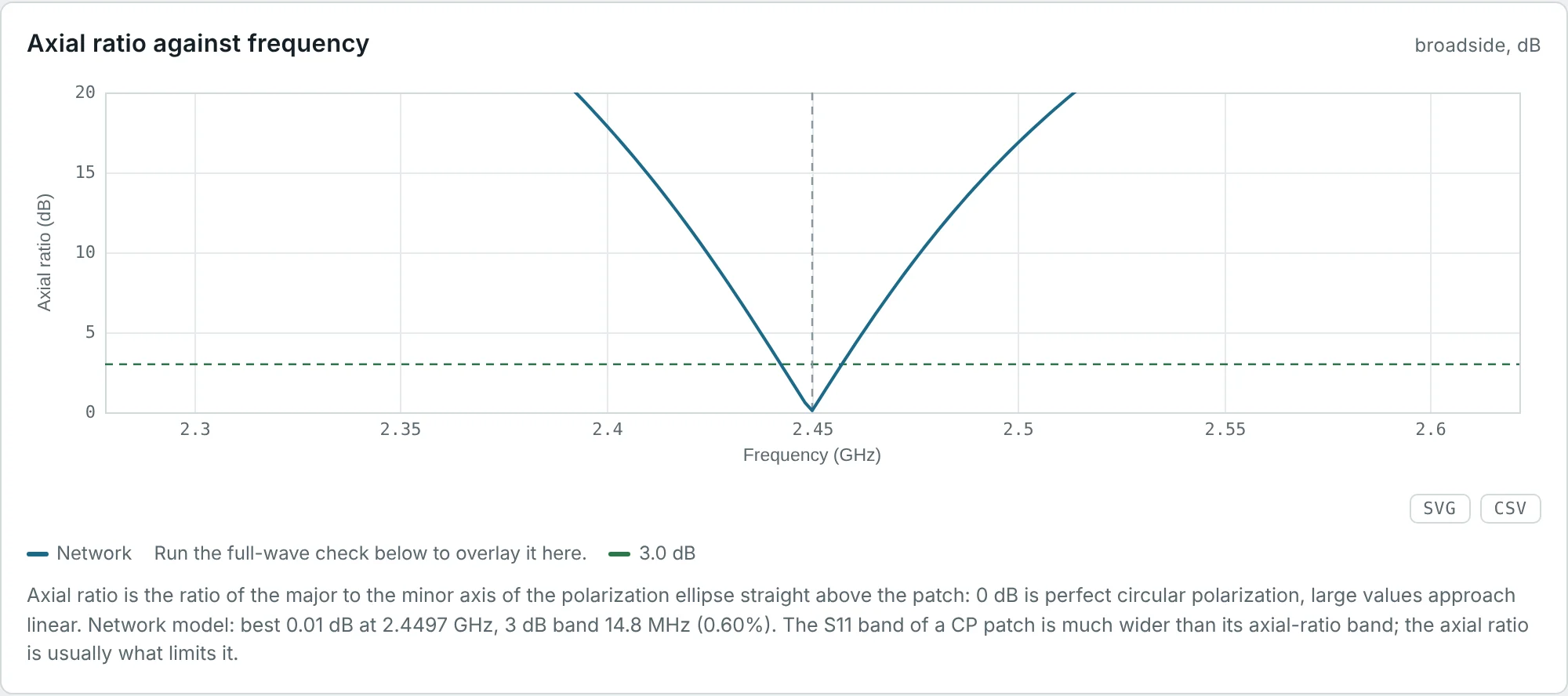
The polarization bandwidth is where the polarization remains as specified — for circularly polarized antennas, usually axial ratio ≤ 3 dB (Part 11). Single-feed CP patches produce circular polarization by exciting two orthogonal modes slightly detuned from each other; the 90° phase difference between them holds only over a narrow band. The calculator's circularly polarized patch shows how dramatic the difference can be:
Absolute and Fractional Bandwidth
Antenna Quality Factor (Q)
The quality factor of an antenna is defined at resonance by the ratio of stored to dissipated energy per radian of the cycle:
| Antenna | Typical Q | Why |
|---|---|---|
| Thick dipole (L/2a ≈ 20) | 4–6 | Large conductor surface spreads the stored energy |
| Thin wire dipole (L/2a ≈ 500) | 8–12 | Field concentrated near the wire |
| Patch on a thin substrate | 20–100 | Energy stored in a cavity between patch and ground |
| Electrically small antenna (ka ≈ 0.3) | 30–1000 | Large reactive near field relative to radiation (Chu limit) |
| Small transmitting loop on HF | 200–2000 | Very small R_r, tiny bandwidth (a few kHz) |
Relationship Between Bandwidth and Q Factor
Suppose a series-resonant antenna is matched at f₀ to a line of Z₀ = R. Using the near-resonance model above, the reflection coefficient is
| Criterion | Maximum |Γ| | Fractional bandwidth |
|---|---|---|
| Half-power (3 dB mismatch) | 0.707 | 1/Q |
| VSWR ≤ 2 | 0.333 | 1/(Q√2) = 0.707/Q |
| S₁₁ ≤ −10 dB | 0.316 | 0.667/Q |
| VSWR ≤ 1.5 | 0.200 | 0.408/Q |
Two consequences are worth remembering. First, loss broadens bandwidth: Q is computed with the total power P = P_rad + P_loss, so adding resistance lowers Q and widens the S₁₁ dip without improving radiation. The FR-4 patch has a wider impedance bandwidth than the Rogers patch for exactly this reason (Example 3). Second, the formula assumes a match at the centre; an antenna that is not matched to Z₀ has a different (usually smaller) bandwidth, as the 146 MHz dipole on 50 Ω shows.
The Chu Limit: How Small Can an Antenna Be?
Enclose an antenna in the smallest sphere of radius a that contains it. Chu expanded the fields outside that sphere in spherical modes and computed the minimum stored energy each mode must carry. For the lowest mode (the one radiated by a short dipole or small loop) and a lossless antenna, the minimum Q is
A half-wave dipole fits in a sphere with ka = π/2, where Q_Chu ≈ 0.9; its actual Q of about 8 is far above the bound because a thin wire uses the sphere's volume poorly. Electrically small antennas (ka < 0.5) are always close to the bound in practice, and their designers trade size, bandwidth and efficiency against each other: small, wideband, efficient — pick two.
The Bode–Fano limit on matching
Can a matching network beat the single-resonance bandwidth? Partly. Bode and Fano showed that for a load consisting of a resistance R and a reactance with quality factor Q, any lossless matching network satisfies
Factors Affecting Antenna Bandwidth
| Factor | Effect |
|---|---|
| Electrical size ka | Smaller antennas have higher minimum Q (Chu limit) |
| Conductor thickness | Thicker dipoles (low L/2a) have flatter reactance and lower Q (Part 7, Fig 1) |
| Substrate thickness h | Patch bandwidth grows roughly in proportion to h/λ |
| Substrate permittivity ε_r | Higher ε_r stores more energy under the patch: narrower bandwidth, smaller patch |
| Loss | Widens the S₁₁ bandwidth by lowering Q — at the cost of efficiency |
| Feed and matching | A matching network can widen bandwidth up to the Bode–Fano limit |
| Antenna type | Travelling-wave and frequency-independent antennas avoid a single resonance altogether |
For a rectangular patch, a widely used design estimate (Jackson and Alexopoulos) of the VSWR ≤ 2 bandwidth of a lossless patch is
Techniques for Bandwidth Enhancement
| Technique | Principle | Typical result |
|---|---|---|
| Fatter conductors, bowties, biconicals | Lower stored energy per radiated power | Dipole: 10% → 30–100% |
| Thicker, low-ε_r substrate (or air) | Lower patch Q | Patch: 2% → 8–10% |
| Stacked or parasitic patches | Two coupled resonances placed side by side | 15–30% |
| U-slot, E-shaped patch, L-probe feed | Extra resonance and compensation of the probe inductance | 20–40% |
| Aperture-coupled feed | Tuning stub and slot resonance add a second pole | 10–25% |
| Broadband matching networks | Multi-section networks approach the Bode–Fano limit | ×1.5–3 the native bandwidth |
| Travelling-wave antennas | No standing wave; current decays along the structure (rhombic, Vivaldi, helix in axial mode) | 2:1 to 10:1 |
| Frequency-independent geometry | Shape defined only by angles (spiral) or self-scaling (log-periodic) | 10:1 to 40:1 |
| Self-complementary structures | Metal and slot have the same shape: Z = η/2 = 188.5 Ω at all frequencies (Mushiake) | Theoretically unlimited |
Worked Examples
Fractional and Ratio Bandwidth
Problem: Express the 2.4 GHz Wi-Fi band (2400–2483.5 MHz) as a fractional bandwidth and the UWB band (3.1–10.6 GHz) as a ratio and as a fractional bandwidth.
A Wi-Fi antenna is a narrowband design problem (one resonance with Q below about 20 will do); a UWB antenna needs a non-resonant geometry such as a planar monopole disc or a Vivaldi.
Dipole Bandwidth from Its Q
Problem: Part 7 estimated Q ≈ 8 for the 146 MHz wire dipole. Predict its VSWR ≤ 2 bandwidth if it were matched to its own resistance at resonance.
Fed directly with 50 Ω, the calculator gives 9.64 MHz (6.6%): the 72 Ω / 50 Ω mismatch at the centre uses up part of the allowed VSWR. A 60 Ω quarter-wave transformer (Part 8) would recover most of the difference over the central part of the band.
Patch Bandwidth from Q: FR-4 vs Rogers
Problem: The calculator reports Q = 27.6 for the FR-4 patch and Q = 44.4 for the Rogers patch, both matched at 2.45 GHz. Predict the −10 dB bandwidths and compare with the calculated 60.7 MHz and 33.9 MHz.
The FR-4 patch is "wider" only because half of its power is burned in the substrate (Part 9). Its realized gain is 3 dB lower across the whole band.
Chu Limit for a 2.45 GHz Module Antenna
Problem: A Bluetooth antenna must fit in a sphere of radius 1 cm. Find the minimum Q and the maximum VSWR ≤ 2 bandwidth for a lossless single-mode antenna.
The 83.5 MHz ISM band needs 3.4%, so a 2 cm antenna can cover it with margin — consistent with the chip and PCB antennas in every Bluetooth product.
Covering LTE Band 8 with a Tiny Antenna
Problem: An IoT antenna for 880–960 MHz must fit in a sphere of radius 2 cm. Can a lossless antenna cover the band with VSWR ≤ 2? What if the efficiency is 40%?
This is why small cellular antennas are either tunable (switching between sub-bands) or accept low efficiency. A matching network can add up to the Bode–Fano gain (Example 6).
What a Matching Network Can Add
Problem: An antenna has Q = 10. Compare its single-resonance −10 dB bandwidth with the Bode–Fano limit for |Γ| ≤ 0.316.
A practical double-tuned (two-resonator) match typically achieves about twice the single-resonance bandwidth, i.e. 12–14% here.
Checking the Patch Bandwidth Formula
Problem: The Rogers patch has ε_r = 3.55, h = 1.524 mm, W = 40.56 mm and L = 32.27 mm at 2.45 GHz (λ₀ = 122.4 mm). Estimate its VSWR ≤ 2 bandwidth.
The formula ignores the 22% of loss in the Rogers patch, which lowers Q and widens the band slightly. For a quick feasibility check it is excellent.
Usable Bandwidth of a CP Patch
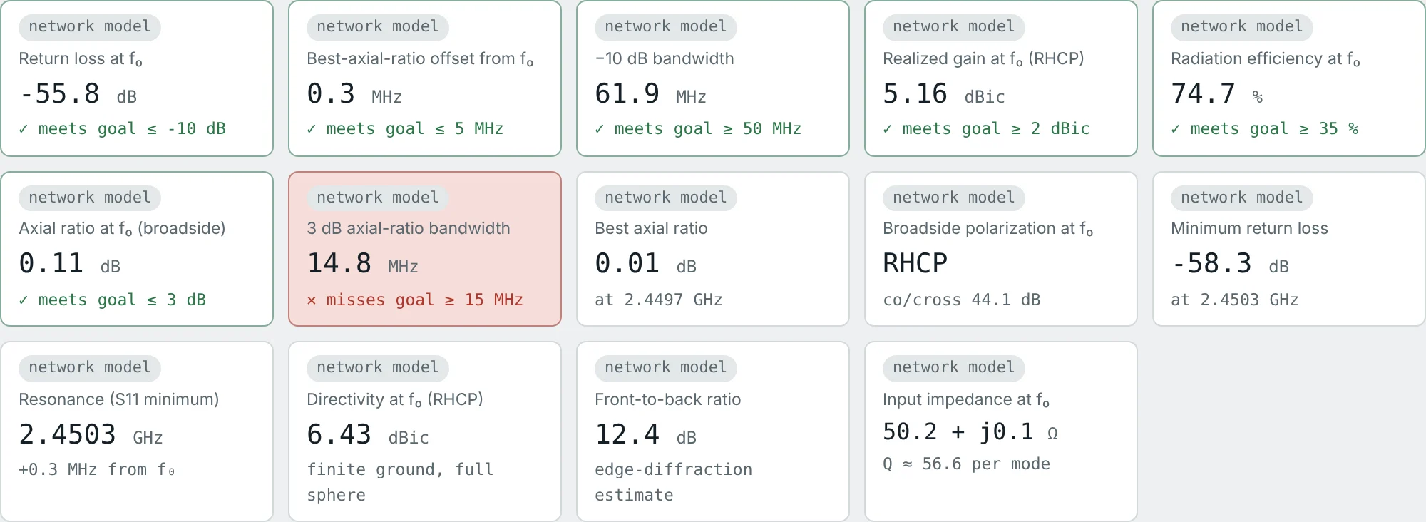
Problem: The corner-truncated CP patch has a −10 dB impedance bandwidth of 61.9 MHz and a 3 dB axial-ratio bandwidth of 14.8 MHz, both centred near 2.45 GHz. What is its usable bandwidth for a CP application?
Too narrow for the full 83.5 MHz ISM band but plenty for a single GNSS signal (GPS L1 is 2 MHz wide). Dual-feed CP patches with a 90° hybrid extend the AR bandwidth to roughly the impedance bandwidth.
Doubling the Substrate Thickness
Problem: Using the patch formula, what happens to the bandwidth of the Rogers patch if two 1.524 mm boards are stacked (h = 3.048 mm)? What else changes?
Lower Q also raises efficiency (Part 9). The costs: a larger inset or probe inductance to match, slightly more surface-wave loss, and a higher cross-polarization level from the thicker substrate.
Sizing a Frequency-Independent Antenna
Problem: A log-periodic dipole array must cover 100–1000 MHz. Its longest element must be about λ/2 at the lowest frequency and its shortest about λ/2 at the highest. Find both element lengths and the ratio bandwidth.
In practice the elements extend about 10–20% beyond these values so that the "active region" of 3–4 resonant elements is complete at the band edges. Bandwidth comes from geometry, not from a low Q (Part 14).
Summary
- An antenna has impedance, pattern, gain and polarization bandwidths; the usable bandwidth is where all requirements hold.
- Fractional bandwidth (f_H − f_L)/f_c describes narrowband antennas; the ratio f_H:f_L describes broadband ones; FBW = 2(r − 1)/(r + 1).
- The −10 dB criterion allows 10% reflected power and 0.46 dB mismatch loss.
- Q = 2ω·max(W_e, W_m)/P; for a matched single-resonance antenna FBW = (s − 1)/(Q√s): 0.707/Q for VSWR 2, 0.667/Q at −10 dB.
- Loss lowers Q and widens S₁₁ bandwidth — a wide dip is not proof of a good antenna.
- The Chu limit Q ≥ 1/(ka)³ + 1/ka bounds small antennas; the Bode–Fano limit bounds what a matching network can add.
- Bandwidth is widened by thicker conductors or substrates, lower ε_r, stacked resonances, broadband matching, and travelling-wave or frequency-independent geometries.
The axial-ratio bandwidth of the CP patch introduced a new requirement: the orientation of the field. Part 11: Antenna Polarization covers linear, circular and elliptical polarization, the axial ratio and the polarization loss factor.
Put It Into Practice
Use the NEXT ANTENNAS calculators to apply the ideas from this article to real antennas.