Introduction to Antenna Efficiency
Every antenna loses some power before it reaches free space. IEEE 145 defines several efficiencies, each covering one loss mechanism, and multiplies them together. The chain from the transmitter to the far field is:
What Is Radiation Efficiency?
Radiation efficiency is the ratio of the power radiated to the power accepted at the antenna terminals. It describes losses inside the antenna, independent of how well it is matched. In terms of the equivalent circuit of Part 7, the same current I_A flows through R_r and R_L:
Conductor Losses and Surface Current
On a good conductor, the tangential magnetic field at the surface is carried by a surface current density J_s = n̂ × H (A/m). Inside the metal, the current decays over a skin depth δ. Inside, J(d) = J₀ e^(−(1+j)d/δ); integrating through the depth, J_s = J₀δ/(1 + j), so |J₀|² = 2|J_s|²/δ². Integrating the ohmic loss |J|²/(2σ) through the depth then gives a simple surface law:
| Metal | σ (MS/m) | δ at 100 MHz | R_s at 1 GHz | Relative to copper |
|---|---|---|---|---|
| Silver | 62 | 6.4 µm | 8.0 mΩ | 0.97× |
| Copper | 58 | 6.6 µm | 8.3 mΩ | 1× |
| Aluminium | 35.5 | 8.4 µm | 10.5 mΩ | 1.28× |
| Brass | 15.9 | 12.6 µm | 15.8 mΩ | 1.91× |
| Stainless steel | 1.39 | 42.7 µm | 53.3 mΩ | 6.46× |
Two practical consequences: plating only needs to be a few skin depths thick (so silver plating over steel works), and surface roughness comparable with δ raises the effective R_s — a real issue for printed antennas above a few GHz, where δ is about 1 µm and electrodeposited copper foil is several µm rough.
Dielectric Losses in Antennas
A lossy dielectric has a complex permittivity ε = ε′ − jε″ = ε₀ε_r(1 − j tan δ), where tan δ is the loss tangent. The time-average power dissipated by a field E inside it is
Dielectric loss dominates in printed antennas on low-cost substrates, in antennas covered by plastic housings close to the radiating edges, in antennas near the human body (tissue has tan δ of 0.3–1), and in dielectric-loaded miniature antennas.
Radiation Efficiency in Terms of Q
Each loss mechanism can be described by its own quality factor, Q_i = ωW/P_i, where W is the total stored energy. Because the powers add, the reciprocals of the Q's add:
Mismatch Efficiency and the Reflection Coefficient
The reflection (mismatch) efficiency is the fraction of incident power that enters the antenna, derived in Part 8:
Total Antenna Efficiency
Total efficiency e₀ is what a system engineer actually cares about: of the power the radio puts into the cable at the antenna, how much ends up as radiation? In over-the-air testing of phones and IoT devices it appears as total radiated power TRP = e₀·P_conducted, and in receive mode as total isotropic sensitivity. The calculator reports the pieces separately for every design:
Difference Between Radiation Efficiency and Total Efficiency
| Radiation efficiency e_cd | Total efficiency e₀ | |
|---|---|---|
| Definition | P_rad / P_accepted | P_rad / P_incident |
| Includes mismatch? | No | Yes |
| Gain relation | G = e_cd · D | G_realized = e₀ · D |
| Can a matching network improve it? | No (it can only add loss) | Yes, by raising e_r |
| Property of | The antenna itself | The antenna in a specific Z₀ system |
| Measured by | Wheeler cap, pattern integration plus S₁₁ correction | Reverberation chamber, OTA TRP measurement |
Factors Affecting Antenna Efficiency
The single most important factor is electrical size. Radiation resistance falls as (L/λ)² while the reactance to be tuned out grows, so the loss in the tuning components rises. Fig 2 shows this for a short dipole made of 2 mm copper wire at 30 MHz, resonated with a loading coil of unloaded Q_coil:
| Factor | Effect |
|---|---|
| Electrical size | Small antennas have tiny R_r and need lossy tuning; efficiency falls steeply below about λ/10 (Fig 2) |
| Conductor material and thickness | R_L ∝ R_s / (conductor perimeter); thin, resistive or rough conductors lose more |
| Substrate loss tangent | Q_d = 1/tan δ: FR-4 patches lose 30–60%; PTFE or ceramic substrates a few % |
| Substrate thickness | Thicker substrates radiate more strongly (lower Q_rad) and so are more efficient, until surface waves take over |
| Ground system | Monopoles over earth lose power in the soil unless many radials are used |
| Nearby lossy objects | Hands, heads and plastic in the reactive near field absorb power (Part 3) |
| Matching components | Inductor Q of 30–60 on PCBs adds noticeable loss to small antennas |
Efficiency of a small loop
Small loops show the size effect even more strongly than short dipoles. A single-turn loop of radius b made of conductor of radius a carries a nearly uniform current, so its loss resistance is simply the conductor length 2πb times R_s divided by the perimeter 2πa of the conductor. Its radiation resistance falls as the fourth power of size (Part 2):
For a 1 m diameter loop of 22 mm copper tube: at 7.1 MHz, R_r = 6.1 mΩ and R_L = 31.6 mΩ, so e_cd ≈ 16% (−7.9 dB); at 14.2 MHz, R_r = 97 mΩ and R_L = 45 mΩ, so e_cd ≈ 68% (−1.6 dB). Doubling the frequency multiplies R_r by 16. This is why compact "magnetic loop" antennas are popular on the higher HF bands and marginal on the lower ones, and why every milliohm in their construction matters.
Surface waves in printed antennas
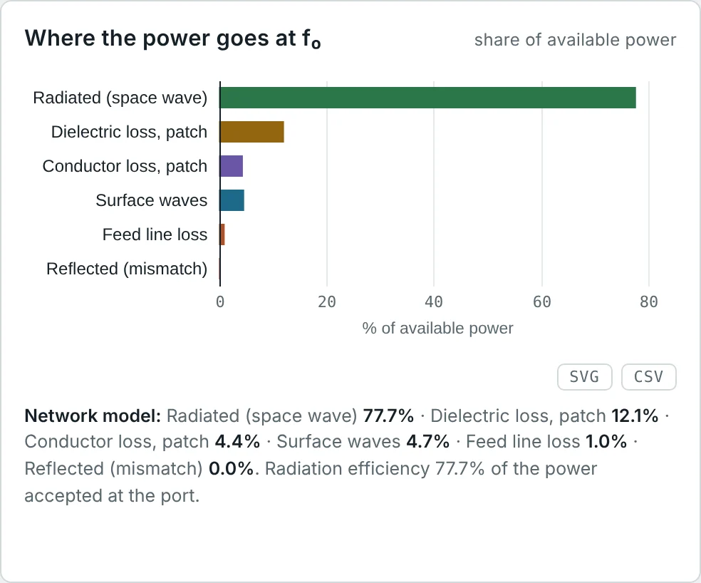
A patch on a grounded substrate also launches surface waves that travel along the dielectric slab instead of radiating. They are not dissipated, but they carry power away from the main beam, diffract at the board edges into unwanted directions (raising the back lobe and cross-polarization) and couple to neighbouring elements. The space-wave efficiency e_sw falls as the substrate becomes thicker or its permittivity higher; for thin substrates (h/λ₀ ≲ 0.02) it stays above about 90%. The calculator's circularly polarized RO4003C patch (h = 1.524 mm, ε_r = 3.55 at 2.45 GHz) has e_sw = 91.6%.
Practical Methods to Improve Antenna Efficiency
- Make the antenna as large as allowed. Use the full available volume; fold or meander rather than shrink.
- Use good conductors with enough cross-section: wide strips, thick wires, copper or silver plating, smooth foil at high frequencies.
- Choose a low-loss substrate (tan δ ≤ 0.004) for printed antennas above about 1 GHz, or use an air-spaced patch.
- Use high-Q tuning components: air-wound coils, vacuum or ceramic C0G capacitors, and as few matching components as possible.
- Improve the ground: 16–120 radials under a monopole, or an elevated ground plane.
- Keep lossy materials out of the reactive near field: clearance from batteries, displays, plastic housings and the body.
- Prevent common-mode current on the feed cable with a balun or choke, so the cable does not become a lossy part of the antenna.
Measuring Antenna Efficiency
The Wheeler cap method encloses a small antenna in a conducting shell that stops it radiating without disturbing its near field. Inside the cap, R_r disappears from the input resistance but R_L remains. For an antenna that behaves as a series RLC near resonance:
Other methods: integrating a full 3D gain pattern (P_rad from the pattern, P_in from the source and S₁₁); reverberation chambers, which compare the antenna with a reference of known efficiency in a statistically uniform field; and radiometric methods that measure the noise temperature (Example 8).
Worked Examples
Total Efficiency of the VHF Dipole
Problem: The 146 MHz copper dipole has e_cd = 99.7% and |Γ| = 0.180 on 50 Ω. Find e_r and e₀ in percent and dB.
Directivity 2.14 dBi − 0.16 dB = 1.98 dBi: exactly the realized gain the calculator reports. A full-size wire antenna is limited by its match, not its losses.
FR-4 vs Rogers: What Efficiency Costs in Gain
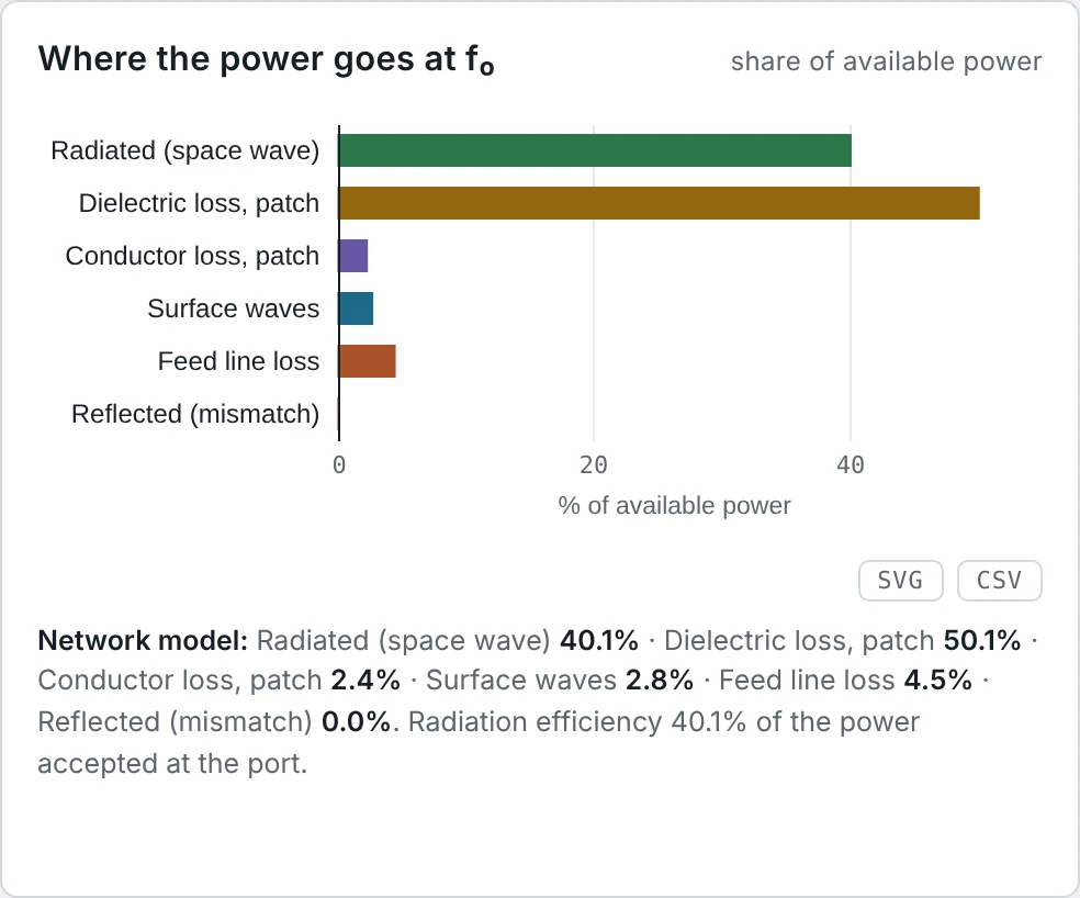
Problem: The FR-4 patch has D = 6.45 dBi and e_cd = 40.1%; the Rogers patch D = 6.72 dBi and e_cd = 77.7%. Find each gain and the difference.
3 dB is the difference between needing two base stations and one. For a 2.45 GHz product the extra substrate cost is usually the cheapest way to buy it.
Breaking Down Patch Losses with Q
Problem: The FR-4 patch has unloaded Q₀ = 27.6 and e_cd = 40.1%; FR-4 has tan δ = 0.02. Find Q_rad and the Q of the remaining losses (conductor plus surface wave).
Dielectric loss (1/Q_d = 0.020) is 55% of the total loss rate 1/Q₀ = 0.036, matching the 50% dielectric loss in the calculator's power budget. Copper loss is minor; the substrate is the problem.
How Much Does Coil Q Matter?
Problem: The 1 m dipole at 30 MHz from Part 7 has R_r = 1.97 Ω and X_A = −1926 Ω. Find the efficiency with a loading coil of Q = 200 and Q = 500 (neglect wire loss).
Improving the coil is worth 3 dB. Doubling the antenna length to 0.2 λ would do far more (Fig 2): R_r rises fourfold and the reactance falls by more than half.
Ground Loss Under a Monopole
Problem: A quarter-wave broadcast monopole has R_r = 36 Ω. With 4 short radials the ground-loss resistance is 10 Ω; with 120 quarter-wave radials it is 2 Ω. Compare the radiation efficiencies.
The ground currents return to the base of the monopole through the soil; radials give them a low-resistance path. The FCC standard for AM stations is 120 radials of λ/4.
Dielectric Q of Common Substrates
Problem: A patch on a substrate radiates with Q_rad = 60 and has negligible conductor loss. Find e_cd for FR-4 (tan δ = 0.02), RO4350B (0.0037) and PTFE (0.0009).
The rule of thumb for a patch: e_cd ≈ 1/(1 + Q_rad tan δ). Efficiency suffers whenever Q_rad·tan δ approaches 1.
Wheeler-Cap Measurement
Problem: A small series-resonant antenna measures R = 52 Ω in free space and R = 6 Ω inside a Wheeler cap. Find its radiation efficiency.
R_r = 46 Ω and R_L = 6 Ω. The method needs no anechoic chamber — just a metal can and a network analyzer.
Why Efficiency Matters for Receiving: Noise
Problem: A GNSS antenna looks at a 50 K sky. Its losses are at 290 K. With e_cd = 50% and a receiver noise temperature of 75 K, how much does the loss degrade the signal-to-noise ratio compared with a lossless antenna?
When the external noise is low (sky, satellites), a lossy antenna is doubly penalized. At HF, where atmospheric noise is thousands of kelvin, the same loss costs only the 3 dB on both signal and noise — almost nothing in SNR.
Total Radiated Power of a Phone
Problem: A phone delivers 23 dBm conducted power to an antenna with total efficiency 30% in talk position (hand and head). Find the TRP.
Operators specify minimum TRP per band; antenna efficiency of 20–50% in use is typical below 1 GHz in smartphones, where the antenna is a small fraction of a wavelength and the hand is in its near field.
Stainless vs Copper on HF
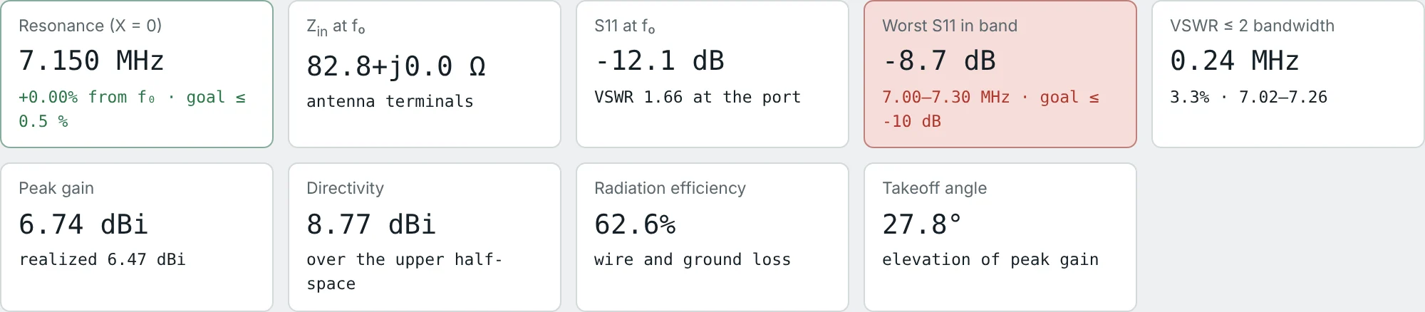
Problem: The calculator gives, for the 7.15 MHz dipole over average earth, radiation efficiency 62.6% (stainless) and 73.6% (copper), with the same directivity 8.77 dBi. Predict both gains and compare with the calculator values 6.74 and 7.44 dBi.
Both include about 22% ground loss, which only a higher antenna or better ground can reduce. On HF, ground loss usually costs more than conductor loss.
Summary
- Total efficiency e₀ = e_r e_c e_d = (1 − |Γ|²) e_cd: mismatch, then conductor and dielectric loss.
- Radiation efficiency e_cd = R_r/(R_r + R_L) = Q₀/Q_rad; it links gain and directivity, G = e_cd D.
- Conductor loss is ½R_s∫|J_s|²dS with R_s = √(πfμ/σ); it concentrates where surface current is high.
- Dielectric loss gives Q_d = 1/tan δ; on FR-4 it halves the efficiency of a patch, on low-loss substrates it is small.
- Electrically small antennas are inefficient because R_r ∝ (L/λ)² while tuning losses grow; coil Q, ground systems and conductor size matter.
- Mismatch efficiency can be fixed externally; radiation efficiency cannot. Efficiency is measured with Wheeler caps, pattern integration or reverberation chambers.
- In receive mode, loss also adds thermal noise, which matters most when external noise is low.
Efficiency and match both depend on frequency. Part 10: Antenna Bandwidth and Quality Factor asks how wide a band an antenna can serve, and how the stored energy measured by Q limits it.
Put It Into Practice
Use the NEXT ANTENNAS calculators to apply the ideas from this article to real antennas.