Introduction to Radiated Power
An antenna fed with P_in watts radiates P_rad ≤ P_in (the rest is lost as heat, Part 9). That radiated power spreads over the sphere around the antenna, but not evenly: the radiation pattern of Part 4 shows its shape. To make the pattern quantitative we need two quantities:
These are the ingredients of directivity and gain (Part 6), of the Friis equation (Part 13) and of every RF-exposure calculation.
The Poynting Vector
Electromagnetic fields carry energy. To see how much, and in which direction, start from Faraday's and Ampère–Maxwell's laws and apply the vector identity ∇·(E × H) = H·(∇ × E) − E·(∇ × H):
The Poynting vector points in the direction of energy flow and its magnitude is the instantaneous power per unit area. For a plane wave in free space, E ⟂ H and |H| = |E|/η, so |S| = |E|²/η.
Average Power Density
Radio fields oscillate billions of times per second, so what matters is the time average over a period. With phasors, a real field is E(t) = Re{E e^(jωt)} = ½(E e^(jωt) + E* e^(−jωt)). Multiplying two such expressions:
In the far field, E and H are in phase, perpendicular, and |H| = |E|/η, so the average power density takes its simplest form:
Solid Angle and the Steradian
An angle in the plane is an arc length divided by radius, measured in radians; a full circle is 2π rad. A solid angle is the three-dimensional equivalent: an area on a sphere divided by the radius squared, measured in steradians (sr). A full sphere is 4πr²/r² = 4π sr.
Radiation Intensity
The radiation intensity U in a given direction is the power radiated per unit solid angle. Because the far-field power density falls exactly as 1/r² while the area subtended by a fixed solid angle grows as r², their product is independent of distance:
Relationship between radiation intensity and power density
| Quantity | Symbol | Units | Depends on r? | Use |
|---|---|---|---|---|
| Power density | S = ½Re{E × H*} | W/m² | Yes, ∝ 1/r² | Exposure, received power S·A_e |
| Radiation intensity | U = r²S | W/sr | No | Pattern, directivity, gain |
| Radiated power | P = ∯U dΩ | W | No | Efficiency, radiation resistance |
Total Radiated Power
Adding up the power in every direction gives the total radiated power. In terms of power density over a sphere of radius r, or equivalently in terms of radiation intensity over the full solid angle:
Standard integrals
Many patterns can be written as, or approximated by, simple powers of sin θ or cos θ. Using the substitution x = cos θ (dx = −sin θ dθ), the integrals reduce to polynomials:
| Radiation intensity U | ∫ over the sphere | P_rad | Typical antenna |
|---|---|---|---|
| B₀ (constant) | 2π · 2 | 4π B₀ | Isotropic (reference only) |
| B₀ sin θ | 2π · π/2 | π² B₀ | Field ∝ √sin θ (exercise pattern) |
| B₀ sin²θ | 2π · 4/3 | (8π/3) B₀ | Short (Hertzian) dipole, small loop |
| B₀ sin³θ | 2π · 3π/8 | (3π²/4) B₀ | Narrower omnidirectional |
| B₀ [cos(π/2·cos θ)/sin θ]² | 2π · 1.2188 | 7.658 B₀ | Half-wave dipole (needs Cin, Part 6) |
| B₀ cosⁿθ, 0 ≤ θ ≤ π/2 | 2π/(n + 1) | 2π B₀/(n + 1) | Patch, horn, dish approximations |
Radiation Intensity in Different Directions
Knowing U(θ, φ) and the distance, the power density in any direction follows immediately: S = U/r². In practice U is rarely given directly. Instead, antennas are described by their gain G(θ, φ) (Part 6), which compares U with the intensity of a lossless isotropic antenna fed with the same power:
Isotropic Radiation and Power Distribution
An isotropic radiator radiates equally in all directions. It cannot be built — no real antenna can produce a transverse field that is uniform over a whole sphere (the "hairy ball" theorem forbids it) — but it is the universal reference. Its radiation intensity and power density are
EIRP and ERP
Regulators and link engineers describe a transmitter by its effective isotropic radiated power: the power that an isotropic antenna would need to produce the same power density in the direction of interest.
Beam Solid Angle
A useful way to summarize how concentrated a pattern is: imagine that all the power were radiated uniformly at the maximum intensity U_max, inside a cone, and nothing outside it. The solid angle of that cone is the beam solid angle Ω_A:
| Pattern | Ω_A (sr) | Fraction of the sphere | 4π/Ω_A |
|---|---|---|---|
| Isotropic | 12.57 | 100% | 1.00 |
| Short dipole (sin²θ) | 8.38 | 67% | 1.50 |
| Half-wave dipole | 7.66 | 61% | 1.64 |
| cos²θ, upper hemisphere | 2.09 | 17% | 6.0 |
| cos⁴θ, upper hemisphere | 1.26 | 10% | 10.0 |
| Pencil beam 10° × 10° | ≈ 0.030 | 0.24% | ≈ 410 |
Average Power for Pulsed and Modulated Signals
The Poynting average over one RF cycle gives the power density of the carrier. Real transmitters switch on and off (radar pulses, TDD frames, push-to-talk) or vary their envelope (AM, OFDM). Exposure limits and heating depend on the power averaged over seconds to minutes, while receivers and breakdown depend on the peak:
Power Density from Several Sources
Power densities from independent transmitters on different frequencies add (their fields are uncorrelated, so the cross terms in |E₁ + E₂|² average to zero). Because the limits depend on frequency, compliance is judged by the sum of the fractions of each limit:
The RF Exposure Calculator has a multi-source step that applies this rule to typical rooftop sites with cellular, 5G, microwave and broadcast transmitters.
Radiation Intensity Calculations: A Recipe
- Get the far field. From a formula (Part 2), a simulator or a measurement, write E = F(θ, φ) e^(−jkr)/r.
- Form U. U = |F|²/(2η) with peak phasors (or |F_rms|²/η).
- Integrate. P_rad = ∫∫U sin θ dθ dφ, analytically for simple patterns, numerically otherwise (Example 6).
- Normalize. U_max/U₀ = 4πU_max/P_rad is the directivity (Part 6); P_rad = ½|I|²R_r gives the radiation resistance (Part 7).
- Scale to distance. S = U/r² in the far field; check that r is beyond the far-field distance (Part 3).
Worked Examples
Power Density of a Plane Wave
Problem: A far-field wave has a peak electric field of 10 V/m. Find the average power density and the peak magnetic field.
The same field quoted as 10 V/m RMS would give twice the power density, 0.265 W/m². Always check whether a field value is peak or RMS — exposure standards use RMS.
Real and Reactive Power Density
Problem: In the near field of an antenna, a transverse E = 5∠0° V/m (peak) and the perpendicular H = 0.02∠−30° A/m. Find the real (time-average) and reactive power densities.
The ratio |E|/|H| = 250 Ω and the 30° phase difference both show that this point is not in the far field. Multiplying |E|²/(2η) instead would give 33.2 mW/m² — a 23% error.
From the Far Field to U and P_rad
Problem: An antenna's far field is E_θ = (10/r) sin θ e^(−jkr) V/m (peak), E_φ = 0. Find U(θ), P_rad and the ratio of the maximum to the average radiation intensity.
This is a short dipole. The ratio 1.5 is its directivity — Part 6 formalizes exactly this calculation.
Integrating U = B₀ sin θ
Problem: An antenna has U = B₀ sin θ with B₀ = 1 W/sr. Find P_rad.
Note the extra sin θ from dΩ: U = B₀ sin θ becomes sin²θ inside the integral. Forgetting the Jacobian sin θ is the most common error in radiated-power calculations.
A Directional cos⁴θ Antenna
Problem: A horn-like antenna has U = 2 cos⁴θ W/sr for 0 ≤ θ ≤ 90° and zero behind. Find P_rad and the power density 100 m away on axis.
An isotropic antenna radiating 2.51 W would give only 20 µW/m² at 100 m. The factor 10 = 2(n + 1) is the directivity of the cos⁴θ pattern.
Numerical Integration: Half-Wave Dipole
Problem: A half-wave dipole with I₀ = 1 A has U = (ηI₀²/8π²)[cos(π/2·cos θ)/sin θ]² = 4.775 F²(θ) W/sr. Estimate P_rad with the midpoint rule using 10° steps.
| θ (midpoint) | 5° | 15° | 25° | 35° | 45° | 55° | 65° | 75° | 85° |
|---|---|---|---|---|---|---|---|---|---|
| F² sin θ | 0.0004 | 0.0111 | 0.0509 | 0.1369 | 0.2788 | 0.4706 | 0.6845 | 0.8734 | 0.9851 |
Smooth patterns integrate very accurately with a coarse grid; patterns with many narrow side lobes need steps finer than the lobe width. The column sum, 3.4917, is doubled because the pattern is symmetric about 90°.
Field of an Isotropic Source
Problem: An isotropic source radiates 100 W. Find the power density and RMS field strength at 1 km.
Check with the dB formula: EIRP = 50 dBm, d = 1 km → 50 − 0 + 44.77 = 94.77 dBµV/m.
Power Density Near a Wi-Fi Access Point
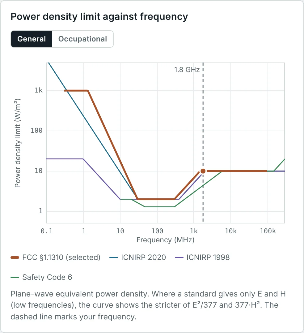
Problem: A 2.45 GHz access point transmits 100 mW into a 5 dBi antenna. Find the power density at 1 m and at 20 cm in the direction of maximum gain, and compare with the 10 W/m² FCC general-public limit.
The 20 cm figure is the separation distance used for mobile-device RF evaluations under FCC rules. At 20 cm and 2.45 GHz (λ = 12 cm) the far-field formula is a reasonable, slightly conservative estimate.
Field Strength of an FM Station
Problem: An FM station has an ERP of 5 kW. Find the EIRP and the field strength in dBµV/m at 1 km and 30 km (free-space estimate).
Real coverage predictions add terrain and ground-reflection losses (ITU-R P.1546), but the free-space value is the starting point and an upper bound for line-of-sight paths.
Exposure in Front of a Cellular Sector
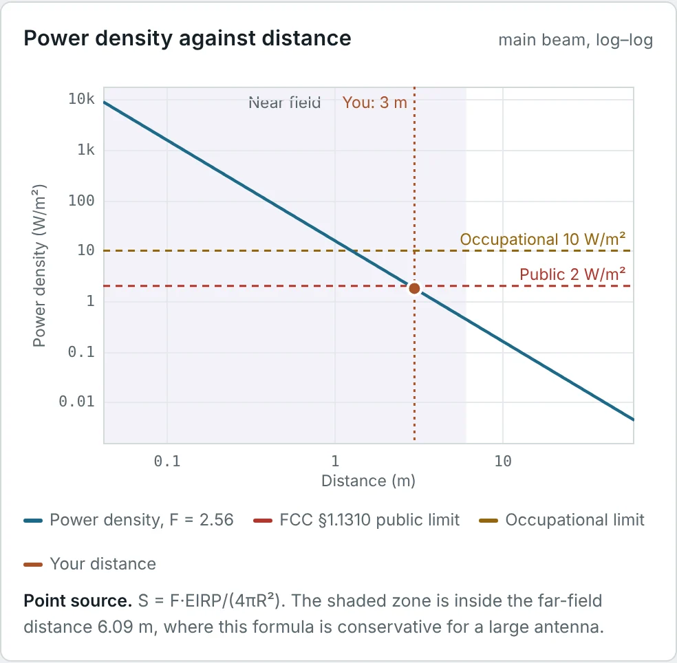
Problem: A sector antenna has an EIRP of 3.57 kW (2 × 40 W, 17.5 dBi, 1 dB feeder). Using the ground-reflection factor F = 2.56, find the power density and E-field 10 m away in the main beam.
The RF Exposure Calculator reports 7.28 W/m² and 52.4 V/m for this case. F = 2.56 = (1 + 0.6)² allows for a ground reflection adding 60% to the field in phase.
Summary
- Poynting's theorem, derived from Maxwell's curl equations, shows that S = E × H is the power flow per unit area.
- For sinusoidal fields the average power density is S_av = ½Re{E × H*}; in the far field S_av = |E|²/(2η) = E_rms²/377.
- Solid angle is measured in steradians, dΩ = sin θ dθ dφ, and a sphere has 4π sr.
- Radiation intensity U = r²S_av (W/sr) is independent of distance and equals |F|²/(2η); normalized, it is the power pattern.
- Total radiated power is P_rad = ∫∫U sin θ dθ dφ; simple patterns integrate in closed form, others numerically.
- An isotropic source has U₀ = P/4π and S₀ = P/(4πr²); any antenna is described by its EIRP, with E_rms = √(30·EIRP)/r and E(dBµV/m) = EIRP(dBm) − 20 log d_km + 44.77.
- The same formulas, with a reflection factor, are the basis of RF-exposure compliance distances.
Comparing U_max with the average intensity P_rad/4π gives a single number for how strongly an antenna concentrates its power. Part 6: Antenna Directivity and Gain defines it, derives it for the standard antennas, and adds losses to obtain gain.
Put It Into Practice
Use the NEXT ANTENNAS calculators to apply the ideas from this article to real antennas.