Introduction to Electromagnetic Radiation
Electromagnetic radiation is energy that leaves a source as a self-sustaining wave of electric and magnetic fields and never returns. It is different from the stored energy around a capacitor or an inductor, which flows back and forth between the circuit and its fields every cycle. An antenna is a structure designed so that a large fraction of the energy delivered to it becomes radiation, and as little as possible stays stored nearby.
Part 1 showed that the radiated power of a short current element is P_rad = 40π²(L/λ)²I₀². Here we derive the fields themselves. They explain where the power goes (the pattern, Part 4), where the stored energy lives (the near field, Part 3), and why the input impedance of an antenna has a reactive part (Part 7).
Relationship Between Electric and Magnetic Fields
Maxwell's equations couple the two fields. Faraday's law says a changing magnetic field produces a circulating electric field; the Ampère–Maxwell law says a changing electric field (displacement current) or a conduction current produces a circulating magnetic field. In phasor form, with time dependence ejωt:
In a travelling plane wave, E, H and the direction of travel are mutually perpendicular, E and H are in phase, and |E|/|H| = η = √(μ/ε). Close to an antenna none of this is true: E and H are out of phase, have components along the direction of travel, and their ratio depends on distance. The transition between the two regimes is the central result of this article.
Time-Varying Fields and Retardation
For a static charge, the electric field everywhere responds instantly to the charge's position. In reality, information about a change travels at c. When the charge moves at time t, an observer at distance r learns about it only at t + r/c. This delay — retardation — is what allows fields to separate from their sources.
Mathematically, it is convenient to work with the magnetic vector potential A, defined by μH = ∇ × A. Substituting into Maxwell's equations with the Lorenz gauge gives a wave equation driven by the current, whose solution is the retarded potential:
This single integral is the foundation of antenna analysis. Every pattern in this series — dipole, array, patch — is an evaluation of it for a particular current distribution J. Simulators such as the Method of Moments solver in our Dipole & Monopole Antenna Calculator first solve for J on the wire and then evaluate this integral.
Accelerating Charges and Electromagnetic Radiation
The simplest radiator is one charge q that briefly accelerates. J. J. Thomson's argument shows why it radiates. Before the acceleration the field lines are straight and radial from the charge's old position; long after, they are radial from the new position. Information about the change travels outward at c, so the two regions are joined by a thin shell in which the field lines are bent sideways. That kink carries a transverse electric field that moves outward. Its strength, obtained by the geometry of the kink, is
Deriving the Larmor formula
The radiated power density is S = E_rad²/η₀ (instantaneous fields), with η₀ = 1/(ε₀c). Integrate it over a sphere of radius r, using dA = 2πr² sin θ dθ:
In an antenna, electrons oscillate sinusoidally along the conductor, so they accelerate continuously and radiate continuously. Their individual speeds are tiny — millimetres per second — but there are around 10²³ free electrons per cubic centimetre of copper, and their accelerations add coherently because they all move in step.
Current Distribution in an Antenna
What an antenna radiates is determined entirely by the current flowing on it. On a thin centre-fed wire, the feed launches waves that travel to the open ends and reflect, so the current is a standing wave. The current must vanish at the free ends, and to a very good approximation the distribution is sinusoidal:
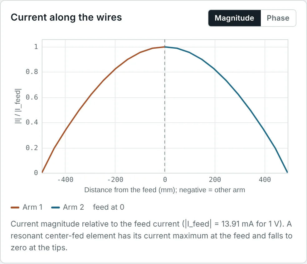
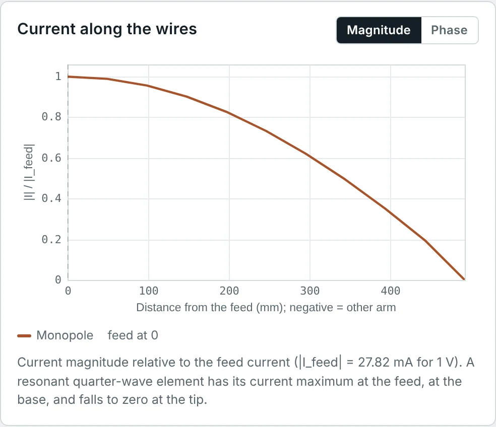
The sinusoidal approximation is excellent for thin wires (diameter below about λ/100). It slightly misrepresents the current near the feed gap and fails to predict the input reactance accurately, which is why numerical methods are used for impedance, while the simple sine gives patterns that are almost indistinguishable from exact solutions.
Radiation from a Short Dipole: The Complete Solution
The Hertzian dipole is a current element of length L ≪ λ along the z-axis carrying a uniform current I. It is the building block of all antennas: any current distribution can be treated as a sum of Hertzian dipoles. Because L is tiny, R ≈ r in the retarded-potential integral and the integral is simply I·L:
Taking the curl, H = (1/μ)∇ × A, only the φ component survives:
Outside the source J = 0, so the Ampère–Maxwell law gives E = (1/jωε)∇ × H:
Three kinds of field
Each field contains terms that fall as 1/r, 1/r² and 1/r³. Factoring out the common 1/r, their relative sizes inside the brackets are 1, 1/(kr) and 1/(kr)²:
| Term | Varies as | Name | Physical meaning |
|---|---|---|---|
| 1 | 1/r | Radiation field | E_θ and H_φ in phase, |E_θ/H_φ| = η: carries real power to infinity |
| 1/(jkr) | 1/r² | Induction field | Biot–Savart magnetic field of the current; 90° out of phase with the radiation term |
| 1/(kr)² | 1/r³ | Electrostatic (quasi-static) field | The field of the oscillating dipole charges; stores electric energy |
All three are equal in magnitude at kr = 1, that is at r = λ/2π ≈ 0.16 λ. Well inside this radius the stored (reactive) terms dominate; well outside it, only the radiation term remains. Part 3 builds the formal near-field and far-field boundaries on this result.
The far-field limit
For kr ≫ 1, drop every term except the 1/r terms:
Radiated power from the far field
The time-average Poynting vector of the far field is radial, S_r = |E_θ|²/(2η). Integrating over a sphere reproduces the Larmor-based result of Part 1, now obtained purely from the fields:
Near Field and Far Field of an Antenna
A compact way to see the transition is the wave impedance Z_w = E_θ/H_φ. Dividing the exact expressions above:
Fig 2 explains why shielding, RF-exposure assessment and near-field communication all depend on distance. A high-impedance near field (dipole) is mostly electric and is stopped well by a thin conductor; a low-impedance near field (loop) is mostly magnetic and passes through thin non-magnetic metal. Beyond a few λ/2π, both fields settle to 377 Ω and become ordinary radiation.
Electromagnetic Wave Propagation from an Antenna
In the far field, every antenna produces a spherical wave of the same general form:
Because the power density falls as 1/r² while the area of a sphere grows as r², the total power crossing any sphere in the far field is constant — this is the conservation statement behind the inverse-square law and behind the free-space path loss of Part 13. At large distances, a small patch of the spherical wavefront is very nearly flat, which is why a distant receiving antenna can treat the incoming wave as a plane wave.
Radiation from Different Antenna Geometries
Dipole of any length
A finite dipole is a chain of Hertzian dipoles, each of strength I(z′)dz′, located at z′. In the far field the distance from each element is R ≈ r − z′cos θ in the phase, and R ≈ r in the amplitude. Adding them up with the sinusoidal current gives a closed form:
| Length L | Main beam | HPBW | Directivity | Comment |
|---|---|---|---|---|
| ≪ λ (Hertzian) | Broadside | 90° | 1.50 (1.76 dBi) | sin θ pattern |
| λ/2 | Broadside | 78.1° | 1.64 (2.15 dBi) | Reference antenna; R ≈ 73 Ω |
| λ | Broadside | 47.8° | 2.41 (3.82 dBi) | Current minimum at the feed: very high input impedance |
| 1.25 λ | Broadside | 32.6° | 3.28 (5.16 dBi) | Maximum broadside directivity of a single wire ("extended double Zepp") |
| 1.5 λ | 42.6° and 137.4° from the wire | 32.8° | 2.23 (3.48 dBi) | Broadside lobe now smaller than the oblique lobes |
Loops, slots and patches
Other geometries follow the same rule — the current (or the aperture field) determines the radiation:
- Small loop: a loop of area A carrying a uniform current is a magnetic dipole. Its fields are the dual of the short dipole: E_φ ∝ sin θ, with radiation resistance R_r = 31 200 (A/λ²)² Ω — even smaller than a short dipole of similar size.
- Slot in a metal sheet: by Babinet's principle, a slot is the dual of a strip dipole of the same shape. Its electric field is across the slot, and Z_slot·Z_dipole = η²/4.
- Microstrip patch: the patch is a resonant cavity. Its fringing fields at the two radiating edges act as two slots half a wavelength apart, whose fields add broadside to the board (Part 14).
- Horns and reflectors: the fields across the aperture radiate like a sum of Huygens sources; the larger the aperture in wavelengths, the narrower the beam (Part 12).
Factors Affecting Antenna Radiation
| Factor | Effect on radiation | Where it is treated |
|---|---|---|
| Electrical size (L/λ) | R_r ∝ (L/λ)² for small antennas; pattern shape and directivity change with length (Fig 3) | Parts 1, 7, 10 |
| Current distribution | Sets the pattern through the radiation integral; tapering reduces side lobes | Part 4 |
| Frequency | Changes the electrical size of a fixed structure; impedance and pattern vary across the band | Part 10 |
| Conductor and dielectric losses | Turn some input power into heat instead of radiation | Part 9 |
| Ground and nearby objects | Reflections add to the direct radiation and reshape the pattern (image theory) | Below, and Part 14 |
| Feed and balun | Unbalanced feeding causes current on the cable shield, which radiates and distorts the pattern | Part 8 |
| Polarization of the currents | Sets the orientation of E in the far field | Part 11 |
The effect of ground: image theory
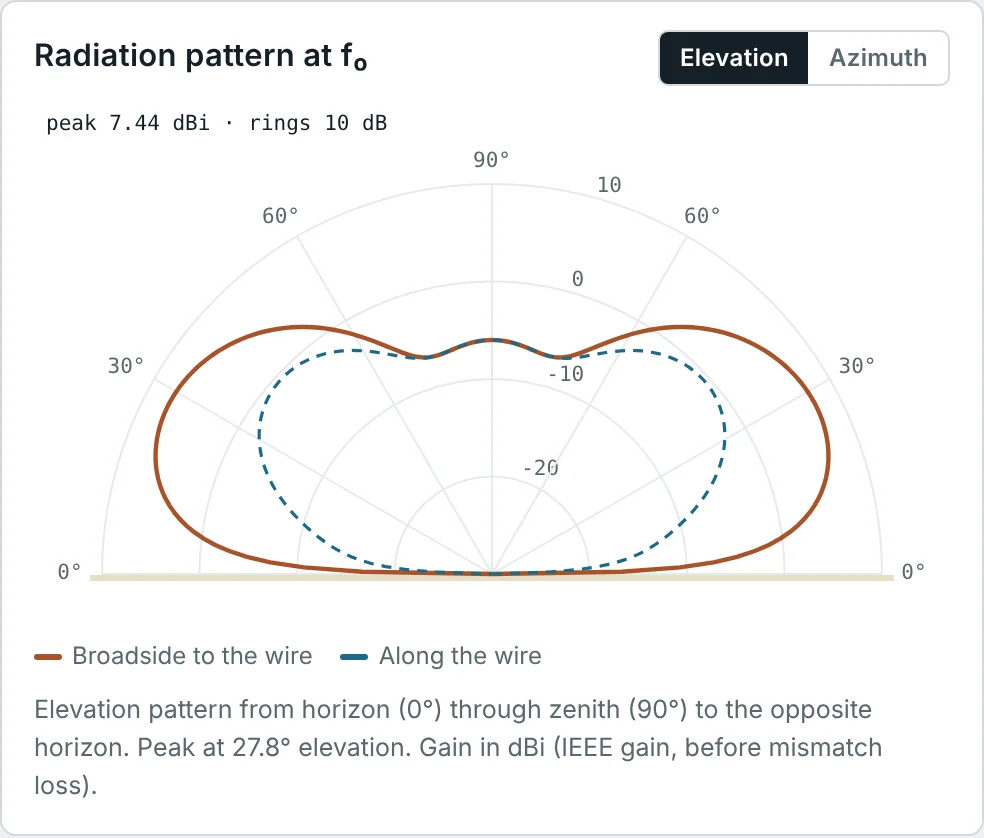
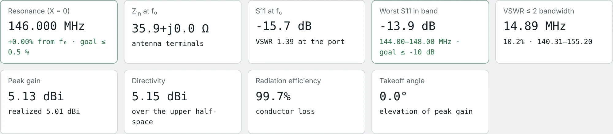
A perfectly conducting plane forces the tangential electric field to zero at its surface. The fields above the plane are then exactly those of the real antenna plus a mirror-image antenna below the plane. A vertical monopole of height h over ground is therefore equivalent, above the ground, to a dipole of length 2h; it radiates the same fields into half the space, so it has half the radiation resistance and twice the directivity of the dipole. The calculator confirms this: a 146 MHz quarter-wave monopole has Z_in = 35.9 Ω (half of the dipole's 71.9 Ω) and 5.13 dBi peak gain (≈ 2.15 + 3 dB).
For a horizontal dipole at height h above ground, the image current is reversed, and the two form a two-element array. The elevation pattern is multiplied by the array factor |2 sin(kh sin Δ)|, where Δ is the elevation angle above the horizon. The first maximum is where kh sin Δ = π/2:
Worked Examples
Radiation Field of an Accelerating Electron
Problem: An electron accelerates at a = 10¹⁸ m/s² (typical in an X-ray tube target). Find the radiation field 1 m away, perpendicular to the acceleration, and the total power it radiates.
One electron radiates almost nothing. An antenna works because ~10²³ electrons per cm³ accelerate together, so their fields add coherently and the power scales as the square of the total current.
Relative Size of the Three Field Terms
Problem: For a Hertzian dipole, compare the magnitudes of the 1/r, 1/r² and 1/r³ terms of E_θ at kr = 0.1, 1 and 10.
| kr | r | Radiation (1) | Induction (1/kr) | Static (1/(kr)²) | Dominant |
|---|---|---|---|---|---|
| 0.1 | 0.016 λ | 1 | 10 | 100 | Static, 99% of |E_θ| |
| 1 | 0.16 λ | 1 | 1 | 1 | All equal |
| 10 | 1.6 λ | 1 | 0.1 | 0.01 | Radiation |
At kr = 10 the reactive terms still alter the field by about 1% in magnitude and a few degrees in phase — the reason the precise far-field boundary of Part 3 depends on how much error is acceptable.
Where the Radiation Term Takes Over
Problem: Find the distance r = λ/2π at 146 MHz (a VHF handheld) and at 13.56 MHz (NFC, RFID). Which region does each system operate in?
A handheld radio is in the radiation zone a metre away, while an NFC reader 4 cm from a card is 90 times closer than λ/2π — deep in the magnetic near field of a loop. NFC couples like a loosely coupled transformer, not like a radio link.
Wave Impedance in the Near Field
Problem: Evaluate the wave impedance of a short electric dipole at kr = 0.5. Is it inductive or capacitive?
The large negative reactance shows that the space around a short dipole stores mostly electric energy, as a capacitor does. Correspondingly, a short dipole's input impedance is strongly capacitive (Part 7). The dual small loop has Z_w = η²/Z_w ≈ 29 + j232 Ω: inductive.
Radiated Power by Field Integration
Problem: A λ/20 current element carries 2 A peak. Compute the radiated power by integrating the far-field Poynting vector, and find R_r.
The ∫sin³θ = 4/3 factor shows that a sin²θ power pattern puts 2/3 of the power that an isotropic source of the same peak would radiate — which is why its directivity is 1.5 (Part 6).
Field Strength of a Half-Wave Dipole
Problem: A half-wave dipole carries I_m = 1 A peak at its feed. Using the dipole far-field formula, find |E| broadside at 1 km and the total radiated power (Part 6 gives P_rad = 36.57 I_m² W).
The rule "E = 60 I/r broadside" for a half-wave dipole is worth remembering: 60 = η/2π. Equivalently, the radiation resistance referred to the current maximum is 2 × 36.57 = 73.1 Ω.
Pattern of a Full-Wave Dipole
Problem: For L = λ, simplify the dipole pattern and find its half-power beamwidth.
Solving F(θ_h) = 0.707 numerically gives θ_h = 66.1°, so HPBW = 2(90° − 66.1°) = 47.8°. Integrating F² gives D = 2.41 (3.82 dBi).
The full-wave pattern is the half-wave pattern multiplied by cos(π/2·cos θ): two half-wave dipoles end to end, in phase — a two-element collinear array (Part 4).
Monopole Impedance by Image Theory
Problem: The 146 MHz dipole in the calculator has Z_in = 71.9 Ω and D = 2.14 dBi. Predict the input impedance and directivity of a quarter-wave monopole on an ideal ground plane, and compare with the calculator.
The same voltage drives half the structure, and the same current produces the same fields in half the space with half the radiated power. A real vehicle roof or radial set is finite, so real monopoles have a slightly tilted beam and lower gain.
Take-Off Angle of an HF Dipole
Problem: A 7.15 MHz dipole is mounted horizontally at h = 21 m. Find the elevation angle of maximum radiation over a perfect ground. What height gives a 15° take-off angle?
Real earth reflects less than a perfect conductor and with a different phase, which lowers the angle slightly, fills in the overhead null and costs about 2 dB of gain.
Radiation Resistance of a Small Loop
Problem: A single-turn loop of 10 cm diameter operates at 30 MHz. Find R_r = 31 200 (A/λ²)² and compare with a 10 cm short dipole at the same frequency (R_r = 20π²(L/λ)²).
Loop radiation resistance falls as the fourth power of size (A²), dipole resistance as the square. Small transmitting loops therefore need very low-loss construction (wide copper tube, vacuum capacitor) and multiple turns (R_r ∝ N²) — while for receiving, the loop's low-impedance magnetic near field makes it less sensitive to nearby electric noise.
Summary
- Radiation comes from accelerating charge; an accelerating charge has a transverse field q a sin θ/(4πε₀c²r) that falls as 1/r and carries away the Larmor power.
- Antenna fields follow from the retarded vector potential A = (μ/4π)∫J e^(−jkR)/R dV, the basis of every pattern and every numerical solver.
- A Hertzian dipole has exact fields with 1/r (radiation), 1/r² (induction) and 1/r³ (quasi-static) terms; they are equal at kr = 1, r = λ/2π.
- In the far field, E_θ = jηkIL sin θ e^(−jkr)/(4πr), H_φ = E_θ/η, and P_rad = (ηπ/3)(L/λ)²|I|².
- The wave impedance is high (capacitive) near a dipole and low (inductive) near a loop; both tend to 377 Ω beyond a few λ/2π.
- A centre-fed dipole of length L has the pattern [cos(kL/2·cos θ) − cos(kL/2)]/sin θ; the beam narrows up to L = 1.25 λ and then splits.
- Current distribution, electrical size, losses, feed and especially ground shape the radiation; image theory explains monopoles (half the impedance, twice the directivity) and the take-off angle of horizontal antennas.
The fields around an antenna change character with distance. Part 3: Antenna Near Field and Far Field divides that space into the reactive near field, the radiating near field and the far field, and derives the boundaries used in measurement and RF-exposure work.
Put It Into Practice
Use the NEXT ANTENNAS calculators to apply the ideas from this article to real antennas.