From first principles to advanced beamforming — our library of guides, tutorials, and deep-dives is free for engineers, students, and enthusiasts worldwide.
Structured topic guides — each covers a complete subject area with articles, equations, and worked examples.
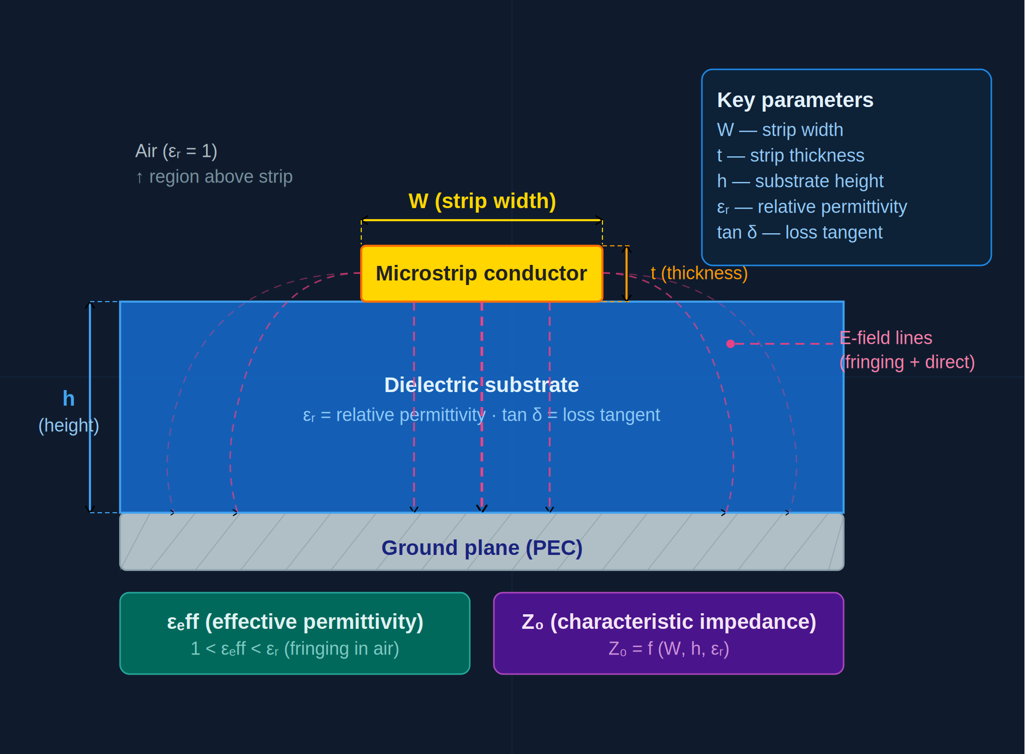
Wave propagation on guided structures — characteristic impedance, reflection, standing waves, and microstrip design.
A practical guide to the most common antenna types — how each works, where it's used, and how to choose the right one for your application.
From electric and magnetic fields to the four equations, electromagnetic waves and boundary conditions — and how they shape lines, waveguides and antennas.
From impedance, reflection coefficient and VSWR to reading the Smith chart and designing L-network and stub matches for real antennas.
How antennas radiate, and every parameter that describes them — patterns, directivity and gain, impedance, S11, efficiency, bandwidth, polarization, aperture and the Friis link.
Part 2: what a transmission line is, the definition of characteristic impedance Z₀ = √(L/C), voltage and current on a line, Z₀ of coaxial cables and microstrip lines, why 50 Ω and 75 Ω systems are used, and the factors that change Z₀.
Read guide →Part 3: load impedance and reflections, the reflection coefficient Γ = (Z_L − Z₀)/(Z_L + Z₀), its magnitude and phase, short, open and matched loads, return loss, S11 and reflected power, with Smith Chart Calculator examples.
Read guide →Part 4: how standing waves form on a mismatched line, voltage maxima and minima, the definition of VSWR, conversions between VSWR, Γ, return loss and mismatch loss, the VSWR circle on the Smith chart, and why VSWR matters.
Read guide →Part 5: the input impedance of a transmission line, impedance transformation as rotation on the Smith chart, λ/8, λ/4 and λ/2 lines, the quarter-wave transformer, short- and open-circuited stubs, and physical line lengths.
Read guide →Part 6: the purpose and history of the Smith chart, how it is constructed from the reflection-coefficient plane, its regions and special points, the impedance and admittance charts, and how to read the combined Z/Y chart.
Read guide →Part 7: normalised impedance and admittance (z = Z/Z₀, y = Y·Z₀), denormalising chart readings, changing the reference impedance from 50 Ω to 75 Ω, and converting normalised values into inductor and capacitor values.
Read guide →Part 8: constant-resistance circles, constant-reactance arcs, constant-conductance and susceptance circles, constant-VSWR circles, the wavelengths-toward-generator scales, radially scaled parameters and constant-Q curves.
Read guide →Part 9: a step-by-step method for plotting impedance on a Smith chart, reading Γ, VSWR and return loss, finding admittance, and following an impedance along a transmission line, with calculator screenshots.
Read guide →Part 10: impedance matching with the Smith chart — conjugate matching, how series and shunt components move the impedance, step-by-step L-network design, four solutions for one load, component values, bandwidth and π/T networks.
Read guide →Part 11: single-stub and double-stub impedance matching — stub position and length on the Smith chart and analytically, short vs open stubs, microstrip lengths on FR-4, the double-stub forbidden region, and stub bandwidth.
Read guide →Part 12: practical Smith chart applications — matching a measured antenna from a Touchstone .s1p file, reading VNA sweeps, how cable loss hides a mismatch, port extension, and stability, gain and noise circles in amplifier design.
Read guide →Part 1 of the Antenna Fundamentals series: what an antenna is, why wireless needs one, radiation from accelerating charges, radiation resistance, receiving antennas and effective aperture, reciprocity, the antenna equivalent circuit and the main antenna families.
Read guide →Reach out directly — we're a small team of RF engineers and we actually reply.